3827 • U2 3/10
9
AC E
lECtriCAl
S
yStEm
S
ECtion
3
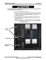
Ammeter
The ammeter indicates the amount of current that is being drawn by the
selected line circuit.
When the appropriate Shore (1 or 2) or Generator circuit breaker group
is ON, all other breakers on the AC Control Center are OFF, and the
voltmeter is reading between 100 and 130 volts in a 120-volt system (210
and 230 volts in a 220-volt system), the ammeter should read zero amps.
As you switch the circuit breakers on the AC Control Center ON and turn
on their associated equipment or turn on equipment plugged into the AC
receptacles, the ammeter readings increase above zero amps. Refer to
Electrical Loads, in this section, for information on the AC electrical system
load limits.
Battery Charger 1
This breaker controls the battery charger that maintains the voltage
level in the engine/accessory batteries. Switch this breaker ON to supply
power to the battery charger. Refer to the OEM information for details on
operating the battery charger.
Battery Charger 2
This breaker controls the battery charger that maintains the voltage level
in the generator battery. Switch this breaker ON to supply power to the
battery charger. Refer to the OEM information for details on operating the
battery charger.
Coffee Maker
This breaker controls the galley’s coffee maker. Refer to the OEM
information for details on operating the coffee maker
Microwave
This breaker controls to the galley’s microwave. Refer to the OEM
information for details on operating the microwave.
Power Available Indicators
These indicators illuminate when the polarity of the shore power source for
the respective line circuit is correct.
Range
This breaker controls the galley’s cooking range. Switch this breaker ON
to supply power to the range. Refer to the OEM information for details on
operating the range.
Receptacles
These breakers control the flow of electricity to the receptacles in
various places in the boat. Switch breakers ON to supply power to these
receptacles.
NOTE: If these circuit breakers are ON but power is not available at any of the
receptacles in this group, the circuit’s GFCI receptacle may have tripped.
https://www.boat-manuals.com/
Summary of Contents for 38 Super Sport
Page 1: ...HIN CVRU2099D010 2010 Version 1 38 Super Sport Owner s Guide https www boat manuals com...
Page 2: ...https www boat manuals com...
Page 4: ...https www boat manuals com...
Page 6: ...https www boat manuals com...
Page 124: ...8 3827 U2 3 10 Warranty and Parts Section 9 Bill of Material https www boat manuals com...
Page 125: ...3827 U2 3 10 9 Warranty and Parts Section 9 Carver Limited Warranty https www boat manuals com...

