51801210406
3
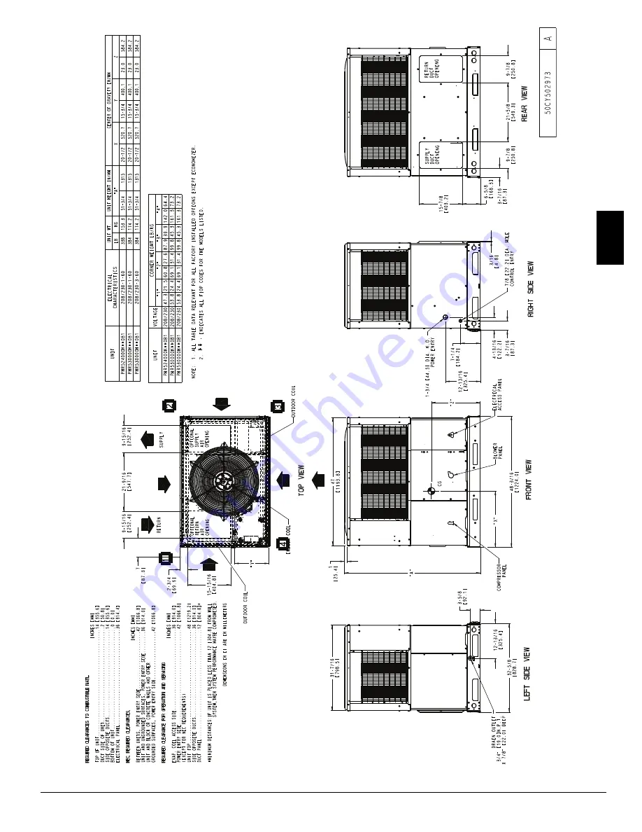
Specifications are subject to change without notice.
A180110
Fig. 2 --
PHR524--30 Unit Dimensions
PHR5
Page 1: ...Fig 1 Unit PHR5 Electrical Controls and Wiring 29 Refrigerant Circuit 30 Evaporator Airflow 30 Metering Device 30 System Information 31 Loss of Charge Switch 31 Check Defrost Thermostat 31 TROUBLESHOO...
Page 2: ...ch method is to be used to remove the downflow panels before rigging and lifting into place The panel removal process may require the unit to be on the ground Step 2 Provide Unit Support IMPORTANT The...
Page 3: ...51801210406 3 Specifications are subject to change without notice A180110 Fig 2 PHR524 30 Unit Dimensions PHR5...
Page 4: ...4 51801210406 Specifications are subject to change without notice Fig 3 PHR536 60 Unit Dimensions PHR5...
Page 5: ...6 406 47 8 1214 32 4 822 2 7 69 30 6 778 46 1 1170 Large CPRFCURB013B00 14 356 14 356 43 9 1116 42 2 1072 Part Number CPRCURB011B00 can be used on both small and large basepan units The cross supports...
Page 6: ...damage or flood the unit Do not install the unit on carpeting or other combustible materials Slab mounted units should be at least 2 in 51 mm above the highest expected water and runoff levels Do not...
Page 7: ...ndensate Drain NOTE When installing condensate drain connection be sure to comply with local codes and restrictions This unit disposes of condensate water through a 3 4 in NPT fitting which exits thro...
Page 8: ...side tabs NOTE These panels are held in place with tabs similar to an electrical knockout Reinstall horizontal duct covers Fig 9 shipped on unit from factory Insure openings are air and watertight NO...
Page 9: ...high voltage L1 L2 and ground lead into the control box 2 Connect ground lead to chassis ground connection 3 Locate the black and yellow wires connected to the line side of the contactor 4 Connect fi...
Page 10: ...6 12 0 5 4 14 8 6 7 REFRIGERANT METERING DEVICE TXV Indoor TXV ORIFICE ID in ID mm 032 2 0 81 2 035 1 038 1 89 1 97 1 042 2 1 07 2 042 2 1 07 2 042 2 1 07 2 052 2 1 32 2 OUTDOOR COIL Rows Fins in Fac...
Page 11: ...at caps on the ports are tight START UP Step 1 Check Cooling and Heating Control Operation Start and check the unit for proper control operation as follows 1 Place room thermostat SYSTEM switch or MOD...
Page 12: ...and let run until system pressures stabilize 4 Measure and record the following a Outdoor ambient air temperature F C db b Liquid line temperature F C at TXV c Discharge high side pressure psig d Suct...
Page 13: ...e Interface Fan Board IFB Jumper wires must use 18 AWG wire with at least 2 64 insulation Cooling Heat Pump Continuous Fan with Advanced Dehumidification For Advanced Dehumidification models to use th...
Page 14: ...6 7 4 1 0 R S S T A C E B D 4 3 0 6 7 4 1 0 R A D11D6 D4 Z2 D4 R11 R8 R7 R9 C8 R15 C1 C2 R1 D1 R12 D2 Q1 C5 QC1 R10 R13 D12 D10 D8 D7 D9 D14 D15 D13 C9 C4 C6 F1 674 674 674 674 K3 K2 K4 K1 QC2 QC5 QC6...
Page 15: ...ow indicates direction of flow Position HPS TXV in Bypass Metering Position C03012 Fig 13 Typical Heat Pump Operation Heating Mode COMPRESSOR ACCUMULATOR OUTDOOR COIL INDOOR COIL LCS LEGEND HPS High P...
Page 16: ...11 0 12 Med Low Pink CFM 831 765 670 586 466 299 BHP 0 11 0 12 0 12 0 13 0 13 0 14 Medium Red CFM 1139 1069 1012 937 870 786 724 626 512 381 BHP 0 22 0 23 0 24 0 24 0 25 0 26 0 26 0 27 0 27 0 28 Med...
Page 17: ...7 1576 1544 1503 1468 1433 1393 1356 BHP 0 42 0 44 0 45 0 46 0 48 0 49 0 51 0 52 0 53 0 55 Med High Orange CFM 1854 1837 1781 1784 1720 1698 1655 1625 1578 1532 BHP 0 56 0 57 0 60 0 59 0 62 0 63 0 64...
Page 18: ...H DEHUMIDIFY 845 880 875 940 975 970 1035 1075 1065 LOW STAGE COOLING 835 850 845 930 945 940 1025 1040 1035 COOLING WITH DEHUMIDIFY 675 685 670 750 760 745 825 835 820 PHR542000KAD0A1 HIGH STAGE COOL...
Page 19: ...700 1800 1900 2000 2100 2200 600 1400CFM 12x20x1 12x20x1 305x508x25 305x508x25 2 0 2 5 0 09 0 14 0 16 0 18 0 25 0 28 0 3 1200 1800 CFM 16x24x1 14x24x1 406x610x25 356x610x25 3 0 3 5 0 10 0 11 0 12 0 13...
Page 20: ...0 00 0 02 0 04 0 06 0 08 0 10 0 12 0 14 0 16 0 18 20 kW 0 00 0 00 0 02 0 04 0 06 0 08 0 09 0 11 0 13 0 15 0 17 0 19 Large Cabinet 36 60 STATIC STANDARD CFM SCFM 1100 1200 1300 1400 1500 1600 1700 180...
Page 21: ...51801210406 21 Specifications are subject to change without notice A13144 Fig 15 Connection Wiring Diagram without Advanced Dehumidification AD FIOP 208 230 1 60 PHR5...
Page 22: ...22 51801210406 Specifications are subject to change without notice A13145 Fig 15 Cont Ladder Wiring Diagram without Advanced Dehumidification AD FIOP 208 230 1 60 PHR5...
Page 23: ...DO NOT DISCONNECT PLUG UNDER LOAD 7 THIS FUSE IS MANUFACTURED BY LITTLE FUSE P N 287003 8 N E C CLASS 2 24V 9 TO USE THE ADVANCED DEHUMIDIFICATION FEATURE CUT JUMPER 1 SCHEMATIC 208 230V 1 60 BLK OF2...
Page 24: ...ROST CYCLES MINUTES 90 SPEED UP JUMPERED TEST PINS USE METAL OBJECT FIELD SPEED UP CYCLE 1 MOMENTARILY SHORT PINS AND RELEASE TO BYPASS COMPRESSOR OFF DELAY 2 SHORT FOR 5 SEC AND RELEASE FOR FORCED DE...
Page 25: ...51801210406 25 Specifications are subject to change without notice A13146 Fig 17 Connection Wiring Diagram 208 230 3 60 PHR5...
Page 26: ...26 51801210406 Specifications are subject to change without notice A13147 Fig 17 Cont Ladder Wiring Diagram 208 230 3 60 PHR5...
Page 27: ...51801210406 27 Specifications are subject to change without notice A170012 Fig 18 Cooling Charging Chart PHR5...
Page 28: ...turn air duct system Always replace the filter with the same dimensional size and type as originally installed See Table 1 for recommended filter sizes Inspect air filter s at least once each month an...
Page 29: ...e unit base Inspect the drain pan and condensate drain line when inspecting the coils Clean the drain pan and condensate drain by removing all foreign matter from the pan Flush the pan and drain troug...
Page 30: ...itch NOTE Because these switches are attached to refrigeration system under pressure it is not advisable to remove this device for troubleshooting unless you are reasonably certain that a problem exis...
Page 31: ...e system Do not unsweat a filter drier from the system Heat from unsweating will release moisture and contaminants from drier into system R 410A Refrigerant Charging Refer to unit information plate an...
Page 32: ...and correct Defective run start capacitor overload or start relay Determine cause and replace Defective thermostat Replace thermostat Faulty condenser fan motor or capacitor Replace Restriction in re...
Page 33: ...EAN AND IN PLACE VERIFY THAT UNIT INSTALLATION IS LEVEL CHECK FAN WHEEL AND PROPELLER FOR LOCATION IN HOUSING ORIFICE AND SETSCREW TIGHTNESS III START UP ELECTRICAL SUPPLY VOLTAGE COMPRESSOR AMPS INDO...
Page 34: ...34 51801210406 Specifications are subject to change without notice PHR5...