background image

PA

4G

: In

sta

lla

tio

n I

ns

tru

ctio

ns

M

an

ufa

ctu

re

r r

es

erv

es

 th

e r

ig

ht 

to

 ch

an

ge

, a

t a

ny

 tim

e, s

pe

cif

ica

tio

ns

 an

d d

es

ig

ns

 w

ith

ou

t n

oti

ce

 an

d w

ith

ou

t o

bli

ga

tio

ns

.

15

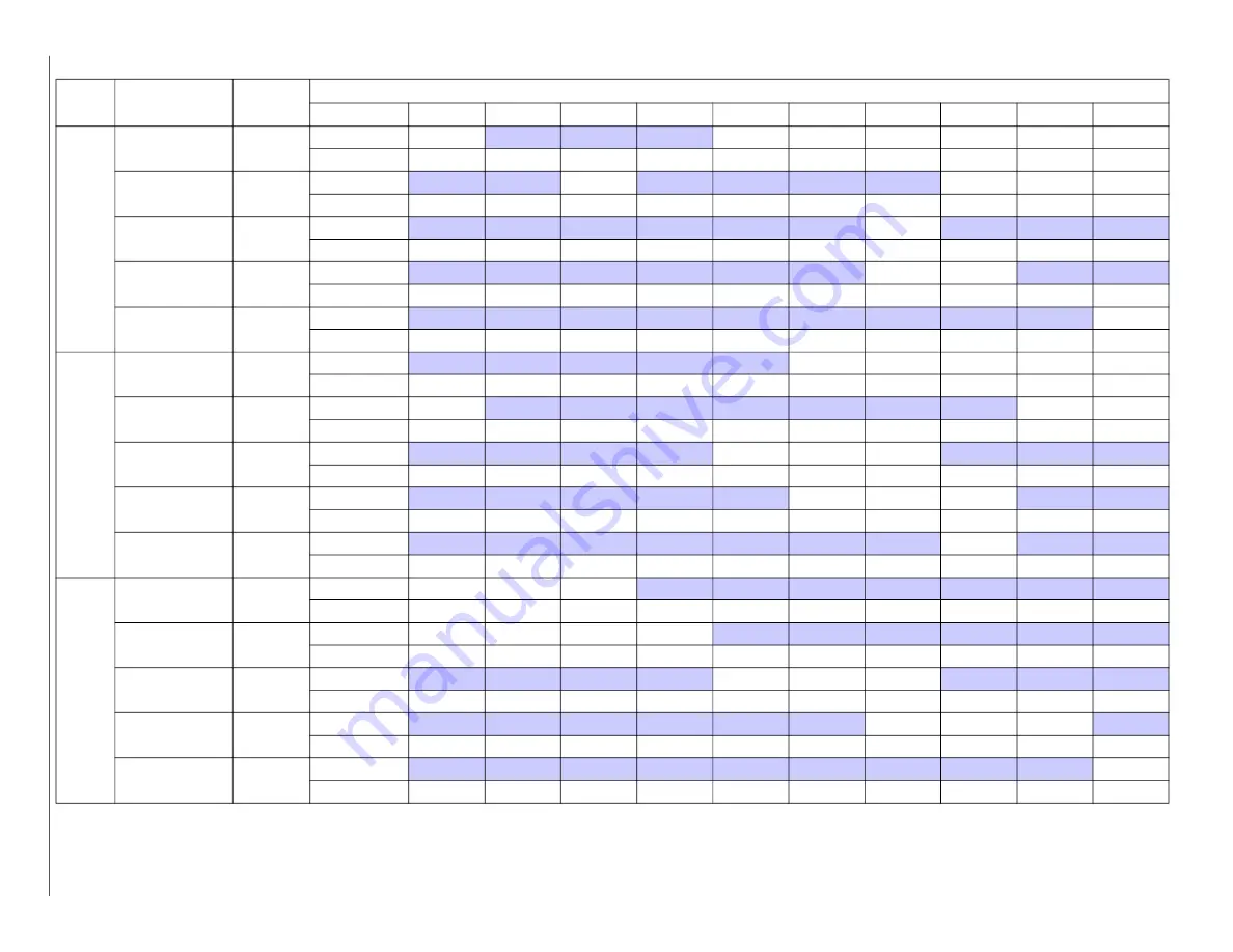
Table 4 – Dry Coil Air Delivery* - Horizontal and Downflow Discharge Sizes 24-60

Unit Size

Motor Speed

Tap

ESP (in. W.C.)

0.1

0.2

0.3

0.4

0.5

0.6

0.7

0.8

0.9

1

24

Low

Blue

CFM

640

553

454

310

---

---

---

---

---

---

BHP

0.07

0.08

0.08

0.09

---

---

---

---

---

---

Med-Low

Pink

CFM

830

758

688

607

514

393

254

---

---

---

BHP

0.12

0.13

0.13

0.13

0.14

0.14

0.15

---

---

---

Medium**

Red

CFM

1080

1025

969

910

852

787

718

638

541

457

BHP

0.21

0.22

0.23

0.23

0.24

0.24

0.25

0.25

0.26

0.27

Med-High

Orange

CFM

1101

1046

993

936

878

816

749

676

599

498

BHP

0.22

0.23

0.24

0.24

0.25

0.26

0.26

0.27

0.27

0.28

High

Black

CFM

1222

1173

1123

1072

1021

967

912

853

787

712

BHP

0.29

0.29

0.30

0.31

0.31

0.32

0.33

0.34

0.34

0.34

30

Low

Blue

CFM

643

552

455

348

225

---

---

---

---

---

BHP

0.09

0.10

0.11

0.11

0.11

---

---

---

---

---

Med-Low

Pink

CFM

817

744

673

597

516

431

325

190

---

---

BHP

0.14

0.15

0.15

0.16

0.17

0.17

0.18

0.18

---

---

Medium

Red

CFM

1159

1104

1045

990

937

878

821

759

693

618

BHP

0.31

0.32

0.33

0.33

0.34

0.35

0.36

0.37

0.37

0.38

Med-High**

Orange

CFM

1201

1147

1095

1037

987

934

877

818

755

671

BHP

0.34

0.35

0.36

0.37

0.37

0.38

0.39

0.40

0.41

0.40

High

Black

CFM

1291

1236

1181

1131

1080

1033

978

909

792

661

BHP

0.41

0.42

0.43

0.43

0.44

0.45

0.46

0.45

0.43

0.40

36

Low

Blue

CFM

1096

1044

994

945

892

837

780

717

664

612

BHP

0.14

0.15

0.16

0.18

0.19

0.19

0.20

0.21

0.22

0.23

Med-Low

Pink

CFM

1151

1103

1056

1002

953

897

845

788

729

678

BHP

0.16

0.17

0.18

0.19

0.20

0.21

0.22

0.23

0.24

0.25

Medium

Red

CFM

1299

1252

1204

1155

1106

1059

1007

959

905

844

BHP

0.22

0.23

0.24

0.25

0.26

0.27

0.28

0.29

0.30

0.31

Med-High**

Orange

CFM

1382

1335

1292

1246

1202

1152

1106

1058

1007

957

BHP

0.26

0.27

0.28

0.29

0.30

0.31

0.32

0.33

0.34

0.35

High

Black

CFM

1530

1485

1442

1398

1354

1309

1263

1217

1169

1120

BHP

0.33

0.35

0.36

0.37

0.38

0.39

0.40

0.41

0.42

0.43

Summary of Contents for PA4G

Page 1: ...manuals be alert to the potential for personal injury Understand these signal words DANGER WARNING and CAUTION These words are used with the safety alert symbol DANGER identifies the most serious hazards which will result in severe personal injury or death WARNING signifies hazards which could result in personal injury or death CAUTION is used to identify unsafe practices which may result in minor...

Page 2: ...ion cant strips roofing and flashing Ductwork must be attached to curb IMPORTANT The gasketing of the unit to the roof curb is critical for a water tight seal Install gasketing material supplied with the roof curb Improperly applied gasketing also can result in air leaks and poor unit performance Curb should be level to within 1 4 in 6 35 mm See Fig 4 This is necessary for unit drain to function p...

Page 3: ...PA4G Installation Instructions Manufacturer reserves the right to change at any time specifications and designs without notice and without obligations 3 A221496 Fig 2 24 30 Unit Dimensions ...

Page 4: ...PA4G Installation Instructions Manufacturer reserves the right to change at any time specifications and designs without notice and without obligations 4 A221497 Fig 3 36 48 Unit Dimensions ...

Page 5: ...E CATALOG NUMBER A IN mm B small common base IN mm B large base IN mm Part Number CPRCURB011B00 can be used on both small and large basepan units The cross supports must be located based on whether the unit is a small basepan or a large basepan C IN mm D IN mm E IN mm F IN mm G IN mm H IN mm Smallor Large CPRFCURB011B00 14 356 10 254 14 356 16 406 47 8 1214 32 4 822 2 7 69 30 6 778 46 1 1170 Large...

Page 6: ...rk joints and roof openings with counter flashing and mastic in accordance with applicable codes Ducts passing through an unconditioned space must be insulated and covered with a vapor barrier If a plenum return is used on a vertical unit the return should be ducted through the roof deck to comply with applicable fire codes See unit rating plate for any required clearances around ductwork Cabinet ...

Page 7: ...er drainage Make sure that the outlet of the trap is at least 1 in 25 mm lower than the drain pan condensate connection to prevent the pan from overflowing See Fig 8 When using a gravel apron make sure it slopes away from the unit Connect a drain tube using a minimum of 3 4 in PVC or 3 4 in copper pipe all field supplied at the outlet end of the 2 in 51 mm trap Do not undersize the tube Pitch the ...

Page 8: ...es Adhere to the following criteria when selecting sizing and installing the duct system 1 Units are shipped for side shot installation 2 Select and size ductwork supply air registers and return air grilles according to American Society of Heating Refrigeration and Air Conditioning Engineers ASHRAE recommendations 3 Use flexible transition between rigid ductwork and unit to prevent transmission of...

Page 9: ...d more than 100 ft 30 5 m from the unit as measured along the control voltage wires use no 16 AWG color coded insulated 35 C minimum wires Standard Connection Locate the seven eight for 3 phase low voltage thermostat leads in 24 volt splice box A gray wire is standard on 3 phase units for connection to an economizer See Fig 10 for connection diagram Run the low voltage leads from the thermostat th...

Page 10: ...ions If the electric heater 24V wires do not have a matching plug cut the 24V wires from the unit receptacle strip the ends and wire nut together to match the schematic connections Factory wires are provided for electric heat staging W1 and W2 W2 and W3 on IFB If room thermostat has only one stage of supplemental heat connect white and violet wires shown in Fig 10 to second stage heat field wire S...

Page 11: ...6 INDOOR BLOWER Nominal Cooling Airflow Cfm Size in Size mm Motor HP RPM 750 10x10 254x254 1 2 1050 950 10x10 254x254 1 2 1050 1150 11x10 279 4x254 1 2 1000 1350 11x10 279 4x254 3 4 1075 1600 11x10 279 4x254 1 0 1075 1750 11x10 279 4x254 1 0 1040 HIGH PRESSURE SWITCH psig Cut out Reset Auto 650 15 420 25 LOSS OF CHARGE LOW PRESSURE SWITCH psig cut out Reset auto N A RETURN AIR FILTERS Throwaway Si...

Page 12: ...start Observe that compressor and outdoor fan shut down when control setting is satisfied and that indoor blower shuts down after 90 second fan time delay expires IMPORTANT Three phase scroll compressors are direction oriented Unit must be checked to ensure proper compressor 3 phase power lead orientation If not corrected within 5 minutes the internal protector will shut off the compressor The 3 p...

Page 13: ...coding on the indoor fan motor leads see Table 3 The additional 4 speed tap wires are shipped loose with vinyl caps and are located in the control box near the interface fan board IFB See Fig 11 Single Cooling Fan Speed Set up Dehumidification feature not used To change cooling speed 1 Remove the vinyl cap off of the desired speed tap wire Refer to Table 3 for color coding Add the wet coil pressur...

Page 14: ...nd G These completed circuits through the thermostat connect contactor coil C through unit wire Y and time delay relay TDR through unit wire G across the 24 V secondary of transformer TRAN The normally open contacts of energized contactor C close and complete the circuit through compressor motor COMP to condenser outdoor fan motor OFM Both motors start instantly A set of normally open contacts on ...

Page 15: ...0 11 0 11 0 11 Med Low Pink CFM 817 744 673 597 516 431 325 190 BHP 0 14 0 15 0 15 0 16 0 17 0 17 0 18 0 18 Medium Red CFM 1159 1104 1045 990 937 878 821 759 693 618 BHP 0 31 0 32 0 33 0 33 0 34 0 35 0 36 0 37 0 37 0 38 Med High Orange CFM 1201 1147 1095 1037 987 934 877 818 755 671 BHP 0 34 0 35 0 36 0 37 0 37 0 38 0 39 0 40 0 41 0 40 High Black CFM 1291 1236 1181 1131 1080 1033 978 909 792 661 B...

Page 16: ...6 0 06 0 07 0 07 0 08 0 08 0 09 Med Low Pink CFM 1437 1395 1351 1307 1265 1221 1176 1132 1084 1039 BHP 0 29 0 30 0 31 0 32 0 33 0 34 0 35 0 36 0 37 0 38 Medium Red CFM 1771 1735 1699 1664 1627 1592 1557 1522 1486 1450 BHP 0 51 0 52 0 53 0 55 0 56 0 57 0 58 0 59 0 61 0 62 Med High Orange CFM 1928 1897 1862 1830 1796 1764 1732 1698 1620 1512 BHP 0 64 0 65 0 67 0 68 0 69 0 71 0 72 0 73 0 71 0 66 High...

Page 17: ...FM 600 700 800 900 1000 1100 1200 1300 1400 1500 1600 1700 1800 1900 2000 2100 2200 600 1400CFM 12x20x1 12x20x1 305x508x25 305x508x25 2 0 2 5 0 03 0 05 0 06 0 08 0 10 0 11 0 13 0 14 0 16 1200 1800 CFM 16x24x1 14x24x1 406x610x25 356x610x25 3 5 0 07 0 08 0 09 0 09 0 10 0 11 0 12 1100 2200 CFM 16x24x1 18x24x1 406x610x25 457x610x25 3 0 4 0 5 0 0 02 0 02 0 03 0 03 0 04 0 06 0 08 0 10 0 11 0 13 0 14 0 1...

Page 18: ...G Installation Instructions Manufacturer reserves the right to change at any time specifications and designs without notice and without obligations 18 A221589 Fig 12 Connection Wiring Diagram 208 230 1 60 ...

Page 19: ...A4G Installation Instructions Manufacturer reserves the right to change at any time specifications and designs without notice and without obligations 19 A221590 Fig 13 Ladder Wiring Diagram 208 230 1 60 ...

Page 20: ...G Installation Instructions Manufacturer reserves the right to change at any time specifications and designs without notice and without obligations 20 A221587 Fig 14 Connection Wiring Diagram 208 230 3 60 ...

Page 21: ...A4G Installation Instructions Manufacturer reserves the right to change at any time specifications and designs without notice and without obligations 21 A221588 Fig 15 Ladder Wiring Diagram 208 230 3 60 ...

Page 22: ...A4G Installation Instructions Manufacturer reserves the right to change at any time specifications and designs without notice and without obligations 22 A221585 Fig 16 Connection Wiring Diagram 460 3 60 ...

Page 23: ...PA4G Installation Instructions Manufacturer reserves the right to change at any time specifications and designs without notice and without obligations 23 A221586 Fig 17 Ladder Wiring Diagram 460 3 60 ...

Page 24: ...tions 24 Superheat charging table is derived from optimum performance point 95_F 35_C outdoor ambient and 80_F 27_C dry bulb 67_F 19_C wet bulb indoor condition Where a dash appears do not attempt to check charge or charge unit under these conditions using the superheat method Weigh in method should be used A150625 Fig 18 Cooling Charging Chart ...

Page 25: ...n in blower compartment d Ensure proper reassembly by marking blower wheel and motor in relation to blower housing before disassembly e Loosen setscrew s that secures wheel to motor shaft remove screws that secure motor mount brackets to housing and slide motor and motor mount out of housing 2 Remove and clean blower wheel as follows a Ensure proper reassembly by marking wheel orientation b Lift w...

Page 26: ...in trough with clear water Do not splash water on the insulation motor wiring or air filter s If the drain trough is restricted clear it with a plumbers snake or similar probe device Outdoor Fan 1 Remove 6 screws holding condenser grille and motor to top cover 2 Turn motor grille assembly upside down on top cover to expose the fan blade 3 Inspect the fan blades for cracks or bends 4 If fan needs t...

Page 27: ... pressure It opens at 650 psig 31 1 kPa High pressure may be caused by a dirty condenser coil failed fan motor or condenser air recirculation To check switch 1 Turn off all power to unit 2 Disconnect leads on switch 3 Apply ohmmeter leads across switch You should have continuity on a good switch Compressor R 410A Refrigerant The compressor used in this product is specifically designed to operate w...

Page 28: ...device coil accumulator or reversing valve Synthetic Roof Precautionary Procedure 1 Cover extended roof working area with an impermeable polyethylene plastic drip cloth or tarp Cover an approximate 10 x 10 ft 3 x 3 m area 2 Cover area in front of the unit service panel with a terry cloth shop towel to absorb lubricant spills prevent run offs and protect drop cloth from tears caused by tools or com...

Page 29: ...erant evacuate system and recharge to capacities shown on rating plate Defective compressor Replace and determine cause Insufficient line voltage Determine cause and correct Blocked outdoor coil Determine cause and correct Defective run start capacitor overload or start relay Determine cause and replace Faulty outdoor fan motor or capacitor Replace Restriction in refrigerant system Locate restrict...

Page 30: ...TS PER INSTALLATION INSTRUCTIONS CHECK ALL ELECTRICAL CONNECTIONS AND TERMINALS FOR TIGHTNESS CHECK THAT INDOOR EVAPORATOR AIR FILTER IS CLEAN AND IN PLACE VERIFY THAT UNIT INSTALLATION IS LEVEL CHECK FAN WHEEL AND PROPELLER FOR LOCATION IN HOUSING ORIFICE AND SETSCREW TIGHTNESS INSPECT TUBING III START UP ELECTRICAL SUPPLY VOLTAGE_______________________________________ COMPRESSOR AMPS ___________...

Reviews: