background image

52

Virtual BACview (see Fig. 34) provides the end-user an interface

to a controller using a laptop. It uses the dongle/cable assembly

found in the technician tool kit (TECH-TKIT) to connect from a

USB port on the laptop to the Rnet port on the 6126 controller. 
The 

Row Count:

 field is for configuring the number of lines on

the screen. The minimum is 4 rows and the maximum is 100 rows.

The 

Comm Port:

 selector allows selection of the COM port

allowing the computer to communicate with the 6126 controller.

Fig. 34 — Virtual BACview

All BACview illustrations in this section are from Virtual

BACview, and may not represent the screen viewed on a hand-

held BACview module, which is limited to four (4) rows of text.

The Virtual BACview software interface provides the same func-

tionality as the hand-held module when connected to a controller,

with some additional benefits, such as the flexibility of using a

mouse or keyboard to modify control parameters, and the added

convenience of changing the screen size (rows only) to display

more information at the same time.
By default, the BACview goes into screen-saver mode after 1

minute of inactivity. Pressing any key reactivates the screen to the

Home Screen.
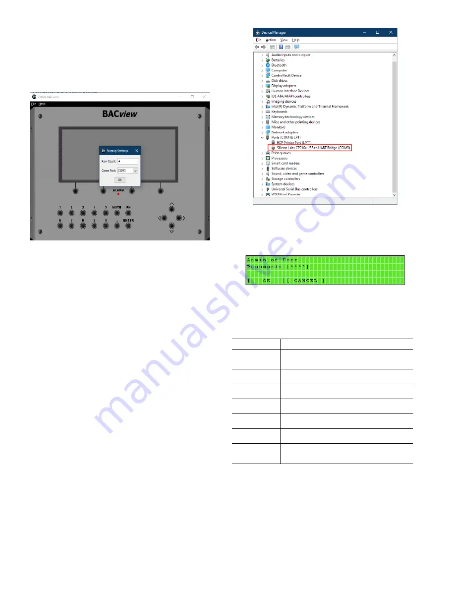
To verify the COM port to use for Virtual BACview, go to the

Device Manager screen, expand the Port (COM & LPT), locate

the Silicon Labs driver, and note the listed COM port. For the ex-

ample shown in Fig. 35, the COM port is COM3. 

Fig. 35 — Virtual BACview COM Port Example

The controller will present the Admin or User Password screen

illustrated in Fig. 36. To proceed, enter 

1111

 and click the 

[OK]

softkey to continue. Click the 

[CANCEL]

 softkey to return to the

previous screen.

Fig. 36 — Admin or User Password Screen

Table 30 provides typical softkey commands encountered while

trouble shooting or configuring the unit.

.

Table 30 — Typical BACview Softkey Commands

SOFTKEY FUNCTION

[OK]

Click this softkey when accepting a configuration 
change

[CANCEL]

Click this softkey to cancel a configuration change

[DECR]

Click this softkey to decrease the parameter value

[INCR]

Click this softkey to increase the parameter value

[

PREV]

Click this softkey to return to the previous screen

[

ALARM]

Click this softkey to review alarms

[

CLOCK-

SET]

Click this softkey to review/change the time and date

Summary of Contents for Omnizone 50BVC

Page 1: ...E DETECTOR FIRE ALARM SHUTDOWN FSD REMOTE OCCUPANCY ROCC RETURN AIR TEMPERATURE RAT SENSOR START UP 32 General 32 CRANKCASE HEATERS CONFIRM THE INPUT POWER PHASE SEQUENCE INTERNAL WIRING RETURN AIR FI...

Page 2: ...stment 71 BELT TENSION ADJUSTMENT Compressor Oil 72 TROUBLESHOOTING 72 SCHEMATICS 74 SENSORS AND INTEGRATION POINTS 80 START UP CHECKLIST CL 1 SAFETY CONSIDERATIONS Installation and servicing of air c...

Page 3: ...trips during cold start up Brownout Surge Power Interruption Protection will shut down the main control board functions if the secondary voltage falls below 18 volts or goes above 30 volts A blink co...

Page 4: ...rect capacity configuration and voltage compared to the unit submittals or product data 2 Verify all modules pieces have been received 3 Verify all required accessories or other field installed compo...

Page 5: ...d the unit 8 Insulate supply and return ducts with 2 in 3 lb density insu lation 9 Round duct is recommended If rectangular ductwork is used keep aspect ratios as small as possible i e as close to squ...

Page 6: ...hardware provided in the main air conditioning section and the instructions below 1 The filter economizer section ships bolted to the main air conditioning section and can be removed in the field high...

Page 7: ...ld Split 30 Ton Fig 3 High Boy Field Split 40 60 Ton 2 3 1 3 2 1 NOTES 1 The filter rack modules item 3 can be field removed from the compressor evaporator module to reduce unit size as shown above 2...

Page 8: ...8 Fig 4 Low Boy Field Split 30 Ton 1 1 2 2 NOTES 1 The filter rack modules item 2 can be field removed from the compressor evaporator module to reduce unit size as shown above 2 Dimensions in inches...

Page 9: ...9 Fig 5 Low Boy Field Split 40 60 Ton 1 3 2 4 1 2 3 4...

Page 10: ...ley Belt Access 18 Minimum 24 Optimum Compressor Access and Electrical Control Access 36 Minimum Blower Blower Blower Motor Blower Motor Compressor Compressor Electrical Control Box Front of Unit Blow...

Page 11: ...RETURN TOP SUPPLY REAR SUPPLY FRONT SUPPLY TOP SUPPLY When WSHP Open controller is installed increase depth by 3 00 inches NOTES 1 All dimensions in inches unless otherwise noted All dimensions withi...

Page 12: ...Connection NOTE 1 Optional hot water coil connections may add up to 3 on both the left and right side of the unit increasing the unit width an additional 6 8 LIFTING SUPPORT RAIL 1 50 CONDENSATE DRAIN...

Page 13: ...TRICAL BOX ACCESS HOT WATER OUT FILTER ACCESS ECONO COIL DX EVAPORATOR HOT WATER COIL ECONO COIL FILTER ACCESS DX EVAPORATOR HOT WATER COIL HOT WATER IN WATERSIDE ECONOMIZER WATER IN WATERSIDE ECONOMI...

Page 14: ...00 13 25 17 50 51 63 LOW VOLTAGE HIGH VOLTAGE ELECTRICAL BOX ELECTRICAL BOX ACCESS 90 25 2 00 VFD BOX BLOWER SECTION ACCESS COMPRESSOR ACCESS 49 75 21 75 9 88 COMPRESSOR ACCESS EVAPORATOR ACCESS EVAP...

Page 15: ...BOX ELECTRICAL BOX ELECTRICAL BOX ACCESS ELECTRICAL BOX ELECTRICAL BOX ACCESS FILTER ACCESS EVAPORATOR ACCESS VFD BOX BLOWER SECTION ACCESS FILTER ACCESS OPTIONAL ECONO COIL HOT WATER OUT DX EVAPORAT...

Page 16: ...VOLTAGE WATER OUT DRAIN WATER IN 14 00 356 7 25 184 10 00 254 TOP VIEW 2 00 51 32 00 813 FILTER RACK 80 00 2032 9 00 229 24 00 610 14 00 356 24 00 610 20 00 508 2 FPT WATER CONN 2 FPT 2 FPT CONDENSATE...

Page 17: ...ROL BOX AND CONTROLLER ACCESS WATER OUT DRAIN WATER IN LOW VOLTAGE HIGH VOLTAGE 10 00 254 TOP VIEW 2 00 51 32 00 813 FILTER RACK 20 00 508 24 00 610 24 00 610 9 00 229 14 00 355 AIR MOTOR AND BELT ACC...

Page 18: ...D AIR AIR AIR 17 25 438 34 50 876 4 00 102 5 00 127 5 00 127 PRE COOLING COIL HOT WATER COIL 0 75 19 DRAIN RIGHT SIDE VIEW 2 50 64 19 00 483 4 00 102 1 00 25 MOTOR AND BLOWER ACCESS BOTH SIDES VFD 1 0...

Page 19: ...AIN WATER IN LEFT SIDE VIEW 32 00 813 14 00 356 28 50 724 1289 0 75 19 DRAIN AIR MOTOR AND BELT ACCESS BOTH SIDES 6 00 152 86 50 2197 27 25 692 54 50 1384 3 50 89 6 00 152 PRE COOLING COIL HOT WATER C...

Page 20: ...3450 3450 3450 RETURN AIR FILTERS Quantity Size in 4 20x32 5x1 4 20x32 5x1 4 20x32 5x1 4 20x32 5x1 Table 3 Physical Data 50BVT V W UNIT 50BVT V W 034 044 054 064 NOMINAL CAPACITY Tons 30 40 50 60 OPER...

Page 21: ...d for a length of at least 15 ft from the unit Direct line of sight from return air grilles into the unit s return should be avoided If return air is to be ducted to an equipment room an elbow should...

Page 22: ...d be used if ambient temperatures are ex pected to fall below freezing or if the loop water temperature is below 55 F while the unit is operating in heating mode Refer to Table 4 which lists freezing...

Page 23: ...r the system pressure expected Pipe coils so that they will drain and provide a drain and vent The fac tory installed VAV controller is not capable of controlling an exter nal heat source including ho...

Page 24: ...2 6 2 5 2 5 100 2 9 3 1 3 1 110 3 5 3 7 3 7 120 4 2 4 2 4 4 130 5 1 4 9 5 1 140 5 9 5 7 5 9 150 6 7 6 6 6 6 160 7 6 7 6 7 5 170 8 6 8 6 8 5 180 9 6 9 6 9 5 FLOW RATE GPM SIZE 020 SIZE 024 SIZE 028 SIZ...

Page 25: ...e low voltage wiring located in the compressor com partment between the two air conditioning sections using the quick connects provided For the supply fan motor connect the 3 phase high voltage wir in...

Page 26: ...dification See Fig 21 for typical thermostat wiring 50BVT V044 064 Only Unit sizes 044 064 have 4 independent refrigerant circuits These units can be controlled using a standard commercial 2 stage the...

Page 27: ...Units Two Stage Cooling C O Y1 Y3 R G C O Y2 Y4 C O Y1 Y2 R G PR2 PR1 PR1 PR2 FIELD SUPPLIED THERMOSTAT UNIT MODULE A UNIT MODULE B Remote Condenser Units Only PR1 PR2 FC1 4 FC1 5 FC1 4 FC1 5 1 2 R G...

Page 28: ...0 2 5 4 38 3 50 024 208 230 3 60 197 253 2 30 1 225 0 2 0 2 6 2 80 1 110 2 30 1 225 0 3 0 2 8 0 83 7 110 2 30 1 225 0 5 0 2 13 4 94 5 110 460 3 60 414 506 2 16 7 114 0 2 0 2 3 1 43 8 60 2 16 7 114 0 3...

Page 29: ...30 1 225 0 2 0 2 6 2 80 1 110 208 230 3 60 197 253 2 30 1 225 0 3 0 2 8 8 85 3 110 208 230 3 60 197 253 2 30 1 225 0 5 0 2 13 5 94 7 110 460 3 60 414 506 2 16 7 114 0 2 0 2 3 1 43 8 60 460 3 60 414 50...

Page 30: ...5 2 18 9 114 1 125 460 3 60 414 506 4 17 9 125 20 2 24 5 126 7 150 575 3 60 518 632 4 12 8 80 7 5 2 7 5 69 4 80 575 3 60 518 632 4 12 8 80 10 2 10 3 75 0 80 575 3 60 518 632 4 12 8 80 15 2 15 1 85 2 1...

Page 31: ...OWN FSD To allow a smoke detector to shut the 50BV unit down field ter minate the sensor on IN 1 of the I O Flex EX8160 expander Use the BACview tool to enable its operation REMOTE OCCUPANCY ROCC The...

Page 32: ...89 26 834 115 46 11 4 182 35 37 22 279 880 41 5 00 25 395 117 47 22 4 006 33 36 11 260 410 43 6 11 24 042 119 48 33 3 838 31 35 00 242 427 45 7 22 22 770 121 49 44 3 679 29 33 89 225 809 47 8 33 21 5...

Page 33: ...nd sensors of each re frigerant circuit This device provides time delays and protects the unit against freezing of the water and refrigerant heat exchangers as well as condensate overflow when the app...

Page 34: ...not energize the CC1 or CC2 outputs the corresponding compressor will remain off the fault LED will flash two times for the LP1 and 4 times for the LP2 and the alarm contact will remain off If the com...

Page 35: ...oving the power from the Y terminal R if set on the DIP switch The compressors will be turned on af ter anti short cycle expires Sequence of Operation CV Units 50BVC Q T V The following sequence of op...

Page 36: ...36 Fig 27 UPM Sequence of Operation SOO Flow Chart...

Page 37: ...power outages PROTECTION Incoming power and network connections are protected by non replaceable internal solid state polyswitches that reset themselves when the condition that causes a fault returns...

Page 38: ...l with the ground wire For a loop powered 4 to 20 mA sensor wire the sensor s positive terminal to the terminal on the I O Flex 6126 controller s Aux Power Out Port Wire the sensor s nega tive termina...

Page 39: ...VDC UI 0 10 V RTD Therm Dry 0 20 mA UI 05 8 9 AI CO2 Sensor Required for demand control ventilation 0 5 VDC UI 0 10 V RTD Therm Dry 0 20 mA UI 04 7 8 AI Leaving Water Temperature Sensor standard 10K...

Page 40: ...0 5 V Therm Dry IN 10 3 4 AI Open UI 0 5 V Therm Dry IN 9 1 2 DI Supply Duct High Static BI Dry contact IN 8 15 16 DI Supply Fan Thermal Overload BI Dry contact IN 7 13 14 DI Water Flow Proving switch...

Page 41: ...Remote Expansion connector 3 Turn on the power to both the I O Flex EX8160 expander and the I O Flex 6126 controller VAV Control Parameters Status and Alarms Control Integral occupancy schedule Exter...

Page 42: ...42 Fig 31 I O Flex 6126 Controller Input Modes and Diagram...

Page 43: ...and re heat opera tions The return air fan can be enabled via the BACview tool and it will be commanded 5 seconds after the supply fan has been en gaged at all times The supply fan can also be set to...

Page 44: ...mulated running time The total fan run time prior to filter service is user configu rable factory default 2000 hrs The filter timer may be reset upon the filter being serviced WATER DIFFERENTIAL PRESS...

Page 45: ...equency 13 1301 Minimum AI 1 0 1302 Maximum AI 1 100 1303 Filter AI 1 1 Sec 1304 Minimum AI 2 0 1305 Maximum AI 2 100 1306 Filter AI 2 1 Sec 14 1401 Relay Output 1 Ready 1402 Relay Output 2 Run 1403 R...

Page 46: ...req 3402 Signal 1 Minimum 0 3403 Signal 1 Maximum 60 50 Maximum motor operating Hertz 3404 Output 1 DPS Form 0 3405 Output 1 DSP Unit SP 3406 Output 1 Minimum 0 3407 Output 1 Maximum 100 3408 Signal P...

Page 47: ...mmable 6Hz Motor Nominal Frequency 13 1301 Minimum AI 1 0 1302 Maximum AI 1 100 1303 Filter AI 1 1 Sec 1304 Minimum AI 2 0 1305 Maximum AI 2 100 1306 Filter AI 2 1 Sec 14 1401 Relay Output 1 Ready 140...

Page 48: ...Output Freq 3402 Signal 1 Minimum 0 3403 Signal 1 Maximum 60 50 Maximum motor operating Hertz 3404 Output 1 DPS Form 0 3405 Output 1 DSP Unit SP 3406 Output 1 Minimum 0 3407 Output 1 Maximum 100 3408...

Page 49: ...perature RAT values as indicated in Table 27 All values have a hysteresis of 2 0 F If discharge air set point reset is required when the value of the discharge air set point is greater than the value...

Page 50: ...out side of normal operating limits Should a High or Low Leaving Water Temperature Alarm occur the call for cool ing will be removed UPM Fault Monitor The controller will monitor both Unit Protection...

Page 51: ...14 flashes per second 14 flashes per second alternating with Run LED Burnout Alternating flashes with Error LED Alternating flashes with the Run LED The controller files have been archived On On Failu...

Page 52: ...ormation at the same time By default the BACview goes into screen saver mode after 1 minute of inactivity Pressing any key reactivates the screen to the Home Screen To verify the COM port to use for V...

Page 53: ...ear allowing the network num ber to be changed 2 Decrease the ARC156 network number to 0 using the increase INCR and or decrease DECR softkeys 3 Click the OK softkey to save the value 4 Move the brack...

Page 54: ...e changed 2 Click the INCR or DECR softkeys to change the value 3 To save the change click the OK softkey To cancel the change click the CANCEL softkey Table 33 Modulating Hot Gas Re Heat Screen Funct...

Page 55: ...Virtual BACview Ctrl 2 The Set Current Time Date 24 hr clock screen see Fig 46 al lows the time and date to be set Fig 46 Set Current Time Date 24 hr clock Screen To change the time and date 1 Move th...

Page 56: ...ss the Alarm screen Table 36 Unit Operation Screen Functions FIELD KEY FUNCTION INFORMATION Unit Status non adjustable Current unit operating status Software Mode non adjustable Manual_On Unit is turn...

Page 57: ...number of fan starts in the last hour Runtime Hours since FILTR service non adjustable Total number of hours since the filters were changed Table 39 Unit Operation Setpoint Screen Functions FIELD KEY...

Page 58: ...oftkey to access the PID Tuning Parameters screen or click the Smoke softkey to access the Smoke Detec tor screen See Table 41 for screen function information Table 40 Supply Fan Lockouts Screen Funct...

Page 59: ...access the Return Fan Lockouts screen Table 42 Smoke Detector Screen Functions FIELD KEY FUNCTION INFORMATION SMOKE DETECTOR STATUS non adjustable Displays the current status of the smoke detector DIG...

Page 60: ...rm softkey to access the Alarm screen or click the UPM2 softkey to access the UPM2 Faults screen See Table 45 for screen function information To reset the Unit Protection Module UPM 1 Move brackets on...

Page 61: ...egistered a fault HP1 Faults Total non adjustable Displays the number of High Pressure switch faults for Circuit 1 since the last reset HP1 Faults Last hr non adjustable Displays the number of High Pr...

Page 62: ...e number of Low Pressure switch faults for Circuit 4 in the last hour FRZ Faults Total non adjustable Displays the number of Freeze alarms since the last reset FRZ Faults Last hr non adjustable Displa...

Page 63: ...n See Table 51 for screen function information Table 48 Outside Air Reset Screen Functions FIELD KEY FUNCTION INFORMATION Outside Air Temperature non adjustable Displays the current outside air temper...

Page 64: ...Functions FIELD KEY FUNCTION INFORMATION Supply Air Temperature non adjustable Displays the current Supply Air Temperature Outside Air Temperature non adjustable Displays the current Outside Air Temp...

Page 65: ...s sor 2 starts in the last hour sliding scale Compressor 2 Runtime hours non adjustable Displays the current Compressor 2 run time in hours Comp 3 Starts Total non adjustable Displays the current numb...

Page 66: ...y to return to the Schedule screen or the Continue softkey to access other days of the week to which to save the schedule SAVE DAILY SCHEDULE Access Weekly Schedule screen Continue softkey The Save Da...

Page 67: ...and end times for DST can be changed Fig 77 Daylight Savings Time Screen 1 Move the bracket using the arrow keys to the value that needs to be changed 2 Press ENTER to change the value The screen soft...

Page 68: ...user to view the current CO2 level Fig 82 Zone CO2 Control Screen Click the softkey to access the CO2 Help screen Click the Stpt softkey to access the Zone CO2 Setpoint screen See Table 61 for Unit Op...

Page 69: ...should be wiped down using a damp soft cloth or sponge with a mixture of warm water and a mild detergent Coil Cleaning Hot water steam and direct expansion coils must be cleaned at least once a year...

Page 70: ...pplied for a longer period GRAVITY FLOW METHOD FIG 85 Do not add solution faster than the vent can exhaust the generated gases When condenser is full allow the solution to remain overnight then drain...

Page 71: ...he shafts at 3 or more locations If the distances are equal then the shafts are parallel Sheave Alignment 1 To check the location of the fixed sheaves on the shafts use a straightedge or a piece of st...

Page 72: ...turn to the compressor s from other system components If neces sary recharge the system as shown in Table 62 Table 62 Oil Recharge TROUBLESHOOTING Refer to Tables 63 and 64 to determine the possible...

Page 73: ...device and replace Check for missing phase Check TXV Check temperature in suction discharge line Unit is Noisy Compressor noise Check TXV and replace if necessary Compressor rotation incorrect check...

Page 74: ...dication and will blink a code as described above Count the number of blinks to determine the lockout condition SCHEMATICS Refer to Fig 89 93 for voltage and wiring schematics NO OF BLINKS DESCRIPTION...

Page 75: ...34 Constant Volume Wiring Schematic UNIT PROTECTION MODULE UPM II INCLUDES BUILT IN 270 300 SECOND RANDOM START TRANSFORMER PRIMARY LEAD COLOR 120 White 208 Red 240 Orange 277 Brown 380 Purple or Yell...

Page 76: ...76 Fig 90 50BVT V044 064 Constant Volume Wiring Schematic DDC UNIT PROTECTION MODULE UPM II INCLUDES BUILT IN 270 300 SECOND RANDOM START 300 SECOND DELAY ON BREAK 120 SECOND LOW PRESSURE BYPASS...

Page 77: ...2 3 4 5 STANDARD COMPONENTS CS COMPRESSOR STATUS 1 4 CURRENT SENSOR 4 IN 4 STAGE UNITS DSS DUCT STATIC SENSOR LWTS LEAVING WATER TEMPERATURE SENSOR RAT RETURN AIR TEMPERATURE SENSOR SAT SUPPLY AIR TEM...

Page 78: ...2 1 4 3 5 6 7 8 9 10 11 12 13 14 15 16 2 1 3 STANDARD COMPONENTS RSS RETURN STATIC SENSOR TO 24 VAC POWER ON CONTROLLER RSS 0 5 VDC COM STANDARD COMPONENTS CWVS CONDENSER WATER VALVE STATUS FA FIRE AL...

Page 79: ...ODULATING HOT GAS REHEAT DX 1 2 1 2 WATER SIDE ECONOMIZER H AI DHS FILTER REHEAT OUTSIDE AIR DAMPER COMPRESSOR START STOP FAN START STOP EWT DUCT HUMIDITY SENSOR DUCT STATIC PRESSURE SENSOR DUCT TEMP...

Page 80: ...AME SNVT DESCRIPTION Alarm Status R Discrete Input 5 alm_status BV 24 nvoAlm Status SNVT_switch 95 Alarm Status of Unit see Current Alarm for more information Allow CWV Alarm R W Coil 1 allow_cwv_alr...

Page 81: ...rs 0 Off 1 Timer Has Expired CMP3_RNTM R Discrete Input 18 comp3_rntm BV 69 Select Compressor 3 Runtime Alarm Status Hours 0 Off 1 Timer Has Expired CMP4_RNTM R Discrete Input 19 comp4_rntm BV 71 Sele...

Page 82: ...VT_count_inc 9 Compressor Stages Configured Status 1 1 Compressor 1 Stage 2 2 Compressor 2 Stages 3 3 Compressor 3 Stages 3 and 4 Stage units only 4 4 Compressor 4 Stages 50BV Default Compressors mode...

Page 83: ...en BV 31 Select Network Alarm Indicat ing Discharge Air Sen sor Failure 0 Normal 1 Alarm Damper Output Cmd R Discrete Input 33 damper_cmd BV 49 nvoDamp erCmd SNVT_switch 95 Damper Output Status 0 Clos...

Page 84: ...rameter to set ELW sensor FAIL 0 Hardwired Sensor Default 1 BAS Sensor Value Enabled Stages R Input Register Float 29 enabled_cl stages AV 68 Select Network Status of the number of Compressor Stages E...

Page 85: ...P3 R Discrete Input 51 lp3_3st BV 6 nvoLp3Ala rm SNVT_switch 95 UPM Board 1 Low Pres sure Alarm Status for Compressor 2 0 Normal 1 LP2 Alarm Active LP4 R Discrete Input 52 lp4_4st BV 55 nvoLp4Ala rm S...

Page 86: ...15 do_two BV 91002 Select Factory Reserved Point Name R W Coil 16 do_three BV 91003 Select Factory Reserved Point Name R W Coil 17 do_six BV 91006 Select Factory Reserved Point Name R W Coil 18 do_fiv...

Page 87: ...0 Normal 1 Overload Alarm RF Overload Status R Discrete Input 75 rtn_blw_ovr load_status BV 98 Select Network Status indicat ing return fan motor over load trip 0 Normal 1 Overload Alarm RH Sensor Sel...

Page 88: ...s AV 16 nvoSys Status SNVT_count_inc 9 General System Status 0 Unoccupied 1 Occupied 2 Fan Only 4 Cooling 5 Transition to Cool 10 Re Heat Unit_mode R W Holding Regis ter Float 49 unit_mode AV 23 Selec...

Page 89: ......

Page 90: ...ight to discontinue or change at any time specifications or designs without notice and without incurring obligations Catalog No 04 53500190 01 Printed in U S A Form 50BV 6SI Pg 90 11 21 Replaces 50BV...

Page 91: ...Y N _______ HAS WATER BEEN PLACED IN DRAIN PAN TO CONFIRM PROPER DRAINAGE Y N _______ ARE PROPER AIR FILTERS IN PLACE AND CLEAN Y N _______ VERIFY THAT THE UNIT IS INSTALLED WITHIN LEVELING TOLERANCE...

Page 92: ...VERAGE VOLTAGE V VOLTAGE IMBALANCE 100 X MAX DEVIATION AVERAGE VOLTAGE IF OVER 2 VOLT AGE IMBALANCE DO NOTATTEMPT TO START SYSTEM CALL LOCAL POWER COMPANY FOR ASSISTANCE III START UP CHECK FAN SPEED A...

Reviews: