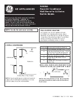
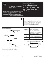
5
Model
Function
Power Supply
Capacity
W
Btu/h
L/h
Electrical data
A
(ID unit only)
W
Electrical data
A
(System)
W
A
max
(*)
W
max
(*)
Type
Fan
RPM (Hi/Lo)
Capacitor
Motor Model Number
Connection
Type
OD (Liquid/Suction)
Cord connection conductor size
(Power supplied to
outdoor unit)
Dimension (WxHxD)
mm
Net Weight
Kg
OD UNIT
42HQG018 HWG455H
Cooling
Heating
230V-1PH-50Hz
4790
5100
16360
17420
1.7
0.19
0.19
45
45
7.3
6.7
1630
1490
x
8.0
2270
1800
Cross flow fan
1150
950
1.8
µ
F, 450V
IC-9430G4KG7A
Flare
1/4”(6.35)
1/2”(12.7)
R,C,Y,O,W2 : 1.0mm
2
S1, S2 : 0.75mm
2
1080x295x185
14
38YL--18---703EC-40
SKY455HJ
42HQG024 HWG605H
Cooling
Heating
230V-1PH-50Hz
6110
7170
20886
24486
2.5
0.19
0.19
45
45
10.7
11
2430
2480
17.0
14.6
3300
2900
Cross flow fan
1250
1050
1.8
µ
F, 450V
IC-9430G4KG7A
Flare
1/4”(6.35)
5/8”(15.88)
R,C,Y,O,W2 : 1.0mm
2
S1, S2 : 0.75mm
2
1080x295x185
14
38YL--24---703EC-40
SKY605HJ
NOTE: • Cooling capacity test is performed through temperature condition based
on 27ºC D.B., 19ºC W.B., in indoor and 35ºC D.B., 24ºC W.B. in outdoor.
• Cooling capacity test is performed at high voltage.
• Specification can change without notice.
Summary of Contents for HWG195C
Page 36: ...35 CONTROL BLOCK DIAGRAM 6 1 42HWG007 009 012 018 024 HWG195C 225C 305C 455C 605C...
Page 37: ...2 42HQG007 009 012 018 024 HWG195 225 305 455 605H SERIES 36...
Page 43: ...b MAIN CONTROL PART 42HWG018 024 42HQG018 024 HWG455 605C HWG455 605H 42...
Page 45: ...c REMOTE CONTROL PART 44...
Page 48: ...47 c CONTROL PCB SOLDERING SIDE 42HWG018 024 42HQG018 024 HWG455 605C HWG455 605H...
Page 49: ...48 d CONTROL PCB COMPONENTS SIDE 42HWG018 024 42HQG018 024 HWG455 605C HWG455 605H...
Page 60: ...59 TROUBLE SHOOTING 10...
Page 64: ...EXPLODED DIAGRAM AND PARTS LIST 12 63...
Page 89: ...Carrier Corporation P N 42KG8K54600 Version 1 0...