31-5000414 Rev. 0 06-20 GEA
Installation Instructions
for your new
Before you begin - Read these instructions
completely and carefully.
IMPORTANT – OBSERVE ALL GOVERNING
CODES AND ORDINANCES.
Note to Installer – Be sure to leave these
instructions with the Consumer.
Note to Consumer – Keep these instructions
with your Owner’s Manual for future reference.
RAD10
For Installation on an
RAB71* (Steel), or RAB80* (Steel),
RAB81* (Steel), RAB77* (Molded),
RAB26* (Steel), or RAB46B* (Steel), RAB78B*
(Molded) Wall Sleeve, or RAB24* (Steel)
*all versions
NOTE:
Parts in this kit will allow for two different types of installations onto the wall sleeve (external or internal.) A
combination of different parts is required. Depending on the type of installation selected, there may be some extra parts.
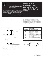
Parts Included
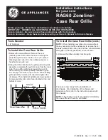
To Install the External Drain
The External Drain Kit is installed on the Zoneline Sleeve
if it desired to direct the sleeve overflow water to the
exterior and completely away from the installation.
1. The gasket should be placed on the cover plate (with
1/2” hole) with screw holes in the gasket lined up with
screw holes in cover plate. Then insert drain tube
(from gasket side) through gasket and cover plate (see
Fig. 1).
2. This assembly may now be installed into either the
left or right drain holes on the rear flange of the
sleeve, using two (2) of the screws (Type A for Metal
cabinet or Type B for Molded) included.
NOTE:
The drain kit may be installed on the sleeve either
before or after the sleeve is installed in the wall, and
with or without the rear protective cover installed on the
sleeve. The stamped rear grille must be removed or the
drain kit installation made before the grille is installed. The
installation of the drain kit may be made from the outside
(rear of sleeve) or from the roomside (inside) by removing
the rear protective cover or rear grille.
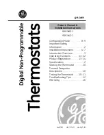
To Install the External Drain (cont.)
3. The solid gasket (without hole) should be properly
placed on the rear of the solid cover plate and the
assembly installed over the drain hole in the sleeve
that it is not used to drain. Using two (2) of the
screws included (Type A or B depending on the type
of sleeve, attach to cabinet (see Fig. 2).
4. A tube or hose 1/2” I. D. (obtained locally) may be
installed onto the drain tube to drain any overflow
water away from the installation (to a gutter ot the
ground).
NOTE:
To redirect the drain tube to another direction
(toward the side, downward, etc.) merely loosen the two
screws, rotate the drain tube to the desired direction
and retighten the screws.
CAUTION
DO NOT point the drain tube above
the horizontal position.
2YHUÀRZUHOLHIGUDLQ
6TXDUHGUDLQKROHV
1HRSUHQHIRDPJDVNHW
6WHHOPRXQWLQJSODWH
´2'GUDLQWXEH
$OWHUQDWH
´ORQJ´2'
VWUDLJKWFRSSHUWXEH
)LJ
+H[+HDGVFUHZV
Enter screw
through the back
of mounting plate
Gasket
Drain Tube
Fig. 1
3” x 1/2” Straight
Tube
(1)
Drain Tube
(1)
Neoprene
Foam Gasket
(3)
Hex Head Screw
for external drains
(4)
Pan Head Screw
for internal drains
(2)
Nut
(2)
Steel Mounting
Plate (2)
Steel Mounting
Plate
(1)