background image

CARRIER CORPORATION ©2019
A member of the United Technologies Corporation family · Stock symbol UTX · Catalog No. 11-808-723-01 · 5/22/2019

ComfortVu

TM


BACnet Thermostat Standard

Model TB-24-HM (24 Vac model)

Installation and Operation Guide

Summary of Contents for ComfortVu TB-24

Page 1: ...TION 2019 A member of the United Technologies Corporation family Stock symbol UTX Catalog No 11 808 723 01 5 22 2019 ComfortVuTM BACnet Thermostat Standard Model TB 24 HM 24 Vac model Installation and Operation Guide ...

Page 2: ... for heating P04 Lock the Fan button P05 Lock the Mode button P06 Lock the On Off button P07 Lock the and buttons Set buttons P08 Functionality of T1 terminals P09 Functionality of IN1 0 terminals P10 Window contact terminals IN1 0 polarity P11 Window contact delay time P12 Door switch terminals T1 0 polarity P13 Door switch delay time P14 Enable Disable Auto change over mode P15 Motion sensor log...

Page 3: ...w T2 temperature sensor readings P84 View T3 temperature sensor readings P85 De ice in cool cut in temperature P86 De ice in cool cut out temperature P87 De ice in heat time P88 De ice in heat break time P89 De ice in heat cut in temperature P90 De ice in heat cut out temperature P91 Compressor delay P98 Display setpoint only hide room temperature P99 One or Two setpoints P101 Screen dimming delay...

Page 4: ... The router s control programs provide trending and alarming of the BACnet Thermostat s data The TB 24 HM thermostat has a white plastic enclosure with an LCD display and buttons for user control It has on board temperature humidity and motion sensing and its on board inputs and outputs are used to control equipment and optional external sensing devices Inputs and outputs are configured using DIP ...

Page 5: ...rmally closed dry contract or 0 10 Vdc analog input or 50 kOhm thermistor 25 C A B Communication RS485 IN1 0 Normally open or Normally closed dry contract or 0 10 Vdc analog input or 50 kOhm thermistor 25 C C R Power 24 Vac Outputs 11 12 13 Digital outputs 3A max 14 Digital outputs 0 3A max 15 and 16 Depends on application Digital output 0 3A max or Analog output 0 10 Vdc 5 mA max not isolated Env...

Page 6: ...rective 2014 35 EU RoHS Compliant 2011 65 EU Australia and New Zealand C Tick Mark AS NZS 61000 6 3 Title 24 compliant if connected to a BMS with custom programming for economizer fault detection CA Prop 65 Warning This product can expose you to chemicals including Styrene and 1 3 Propane sultone which are known to the State of California to cause cancer For more information go to www p65warnings ...

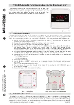
Page 7: ...TB 24 HM Dimensions 7 ...

Page 8: ...d Low Medium High Auto Press and hold to activate fan on demand Press to select System Mode Cool Heat Auto Press to turn unit On or Off Ambient Setpoint indication temperature Ambient humidity indication Thermostat On Off indication System MODE indication Clock Weekdays Fan only Cooling Heating Auto mode Press to switch between temperature scales ºC ºF Press and hold to enter weekly program settin...

Page 9: ...erature for cooling will appear on display 2 Use the or button to adjust the setpoint for cooling 3 Press the Mode button or wait 3 seconds and the setpoint temperature for heating will appear on display 4 Use the or button to adjust the setpoint for heating Notes The setpoint for cooling must be higher than the setpoint for heating For humidity setpoint see Technician Setting P197 OFF ON Celsius ...

Page 10: ...edium speed available in 3 speeds configuration Selecting Fan speeds for 2 and 3 fan speeds configuration Low Medium High Auto Press the Mode button to switch between system modes Notes During demand for cooling or heating the active mode will flash In Auto mode the active mode icon Cool or Heat will appear on display Auto mode is not available in 2 Pipe system configuration Selecting system mode ...

Page 11: ... alternates between AL and room temperature Operating instructions cont Temperature Time Normal work Freeze protection Cut in Cut out Economy mode 11 Activate Economy mode by triggering a window contact door switch key tag remote economy switch the built in PIR sensor passive infrared sensor or through communication binary value UnoccupiedByNetwork When Economy mode is active the thermostat will u...

Page 12: ...sor Soft start in heat sensor Deicing in cool Door switch Key tag Whenever there is demand for cooling and the outdoor temperature conditions allow the operation of the economizer it will operate together with the regular cooling system and will not replace it Economizer will start when both of the following conditions are satisfied Teconomizer temperature Room temperature Cool differential band 2...

Page 13: ...day to Friday and another for Saturday and Sunday Daily events Each daily program can use 2 or 4 schedule events per day set by Technician Setting P108 There are two options for settings the schedule events set by Technician Setting P109 EU Type Start time and Stop time US Type Start time setpoint temperatures system mode and fan speed Enabling Disabling Overriding the program Select 00 in Technic...

Page 14: ...ed Adjusting the time and day of the week The BACnet Thermostat will respond to a BACnet time sync but you can manually set it using the following instructions 1 Press and hold the C F Prog button The word Clock will appear on display and the HOURS will flash Hours 2 Use the and buttons to adjust the hours Minutes 3 Press the C F Prog button again The MINUTES will flash 4 Use the and buttons to ad...

Page 15: ...n The MINUTES will flash 4 Use the and buttons to adjust the start time minutes of the first event Stop time 5 Press the C F Prog button again T the word Stop will appear on display and the HOURS will flash 6 Use the and buttons to adjust the stop time hours of the first event 7 Press the C F Prog button again The MINUTES will flash 8 Use the and buttons to adjust the stop time minutes of the firs...

Page 16: ... again The MINUTES will flash 4 Use the and buttons to adjust the start time minutes of the first event System mode 5 Press the C F Prog button again The system MODES will flash 6 Use the and buttons to select the system mode of the first event 7 Press the C F Prog button again The FAN SPEEDS will flash 8 Use the and buttons to select the fan speed of the first event Follow the steps above for set...

Page 17: ...ts the setpoint for cooling and then the setpoint for heating 2 Use the and buttons to select the system mode of the first event Follow the steps above for the other schedule events of the same day Prog 2 for two events per day or Prog 2 3 and 4 for four events per day Follow the steps above for all the other days 17 Weekly program cont ...

Page 18: ...Device Instance Number is 16075 Note If you change the MAC address you must cycle the thermostat s power to reset the BACnet Device Instance Number You can override the automatically generated BACnet Device Instance Number using the i Vu application an Analog Network Output microblock in a control program or some other BACnet utility Write the new BACnet Device Instance Number to the present_value...

Page 19: ... from back panel by pressing the tab located in the top of the unit and pulling the back panel off of the two bottom tabs B Do one of the following If using an electrical box mount the included wallplate to a standard 4 x 2 electrical box using the two larger mounting screws then mount the thermostat to the wallplate using the three smaller mounting screws Insert the screw cap into the wallplate s...

Page 20: ... and DIP switch jumper settings pages 25 through 39 11 12 13 14 T1 0 B A 0 IN1 15 16 C R MS TP Communication RS485 BACnet For IN1 0 inputs Dry contact 10 Vdc input or 50 kOhm thermistor See Technician Setting P9 page 42 Power supply 24 Vac CAUTION Do not connect line voltage to a thermostat that does not show the following symbol 20 Terminals ...

Page 21: ...sition 1 Analog output Position 3 Digital output 4 3 2 1 8 7 6 5 4 3 2 1 6 5 4 3 2 1 SW4 SW3 SW1 21 SW4 2 Enable Disable PIR detector JP3 JP2 3 1 3 1 End of line End of line Communication line SW1 1 through SW1 6 and SW3 1 through SW3 8 See Wiring and DIP switch jumper settings pages 25 through 39 SW4 1 Without valves control in FC config Enable OFF Open Disable ON Closed SW4 3 Not used Always OFF...

Page 22: ...ompressors Heat pump Fan speeds Fan VFS Economizer Humidifier Dehumidifier Reheat Dehumidify AC Configurations without humidification dehumidification AC Configurations with humidification dehumidification 22 Find the configuration you want in the tables below then find that configuration number 1 through 19 on the Wiring and DIP switch jumper settings pages starting on page 25 AC configurations C...

Page 23: ...ment 2nd stage Cool Heat valve Humidifier Dehumidifier Reheat Dehumidify Cool Heat valve PID Fan VFS Fan speeds Economizer Humidifier Dehumidifier Reheat Dehumidify 23 Find the configuration you want in the tables below then find that configuration number 20 through 30 on Wiring and DIP switch jumper settings pages starting on page 31 FC configurations for 2 pipe systems 20 Configuration Outputs 2...

Page 24: ...e Humidifier Dehumidifier Reheat Dehumidify Fan VFS Fan speeds Economizer Floor heating PID PID PID PID Cool valve Cool valve PID Heat valve Heat valve PID Humidifier Dehumidifier Reheat Dehumidify 24 Find the configuration you want in the tables below then find that configuration number 31 through 47 on the Wiring and DIP switch jumper settings pages starting on page 34 FC configurations for 4 pi...

Page 25: ... JP2 3 Jumpers JP2 JP3 for analog outputs 1 3 1 JP3 JP2 3 1 3 1 JP3 JP2 3 1 3 1 JP3 JP2 3 1 3 1 25 Heat element 1 3rd stage heat Fan medium or Economizer Fan medium or Economizer 12 Outputs See drawing on page 21 for DIP switch and jumper locations Control Fan on off Heat elements Heat pump Compressors Economizer 24 Vac 0 5A max 5 5 2 3 3 3 3 2 2 2 2 1 SW3 1 SW3 2 Fan speeds 2 speeds Low and High ...

Page 26: ...gurations AC systems Outputs See drawing on page 21 for DIP switch and jumper locations Fan VFS 0 10 Vdc 0 5 mA Not isolated Control Fan on off Heat elements Heat pump Compressors Economizer 24 Vac 0 5A max 1 SW3 1 SW3 2 Fan speeds 2 speeds Low and High SW3 1 OFF SW3 2 ON 3 speeds Low Med and High SW3 1 OFF SW3 2 OFF 2 SW3 4 HP Heat pump ON Heat pump active in cool OFF Heat pump active in heat HC ...

Page 27: ...P2 3 Jumpers JP2 JP3 for analog outputs 1 3 1 JP3 JP2 3 1 3 1 27 Wiring and DIP switch jumper configurations AC systems Outputs Control Fan on off Heat elements Heat pump Compressors Economizer 24 Vac 0 5A max See drawing on page 21 for DIP switch and jumper locations 5 Economizer option SW1 6 ON 5 3 3 2 2 2 SW3 4 HP Heat pump ON Heat pump active in cool OFF Heat pump active in heat HC not heat pu...

Page 28: ...onomizer Fan high Fan low Heat element 2nd stage heat JP3 JP2 3 Jumpers JP2 JP3 for analog outputs 1 3 1 JP3 JP2 3 1 3 1 JP3 JP2 3 1 3 1 JP3 JP2 3 1 3 1 28 Wiring and DIP switch jumper configurations AC systems w wo Humidifier for humidification with Reheat for dehumidification Outputs Humidifier 0 10 Vdc 0 5 mA Not isolated Control Fan on off Heat elements Heat pump Compressors Economizer 24 Vac ...

Page 29: ...1 JP3 JP2 3 1 3 1 29 Wiring and DIP switch jumper configurations AC systems with Humidifier for humidification Outputs Humidifier 0 10 Vdc 0 5 mA Not isolated Control Fan on off Heat elements Heat pump Compressors Economizer 24 Vac 0 5A max See drawing on page 21 for DIP switch and jumper locations 2 2 Economizer option SW1 6 ON 5 5 2 3 3 2 SW3 4 HP Heat pump ON Heat pump active in cool OFF Heat p...

Page 30: ...ifier Dehumidifier 6 5 4 3 2 1 Compressor Heat pump Compressor JP3 JP2 3 Jumpers JP2 JP3 for analog outputs 1 3 1 JP3 JP2 3 1 3 1 JP3 JP2 3 1 3 1 JP3 JP2 3 1 3 1 30 Wiring and DIP switch jumper configurations AC systems with Humidifier for dehumidifier Outputs Humidifier Dehumidifier 0 10 Vdc 0 5 mA Not isolated Control Fan on off Heat elements Heat pump Compressors Economizer 24 Vac 0 5A max See ...

Page 31: ... JP3 for analog outputs 1 3 1 JP3 JP2 3 1 3 1 JP3 JP2 3 1 3 1 JP3 JP2 3 1 3 1 31 Wiring and DIP switch jumper configurations FC systems 2 pipe Outputs Fan VFS PID valves 0 10 Vdc 0 5 mA Not isolated Control Fan on off Heat elements Cool Heat valves Economizer 24 Vac 0 5A max See drawing on page 21 for DIP switch and jumper locations 2 1 1 5 5 Economizer option SW1 6 ON 5 2 2 5 3 3 3 3 1 SW3 1 SW3 ...

Page 32: ... 5 4 3 2 1 JP3 JP2 3 Jumpers JP2 JP3 for analog outputs 1 3 1 JP3 JP2 3 1 3 1 JP3 JP2 3 1 3 1 JP3 JP2 3 1 3 1 32 Wiring and DIP switch jumper configurations FC systems 2 pipe with Humidifier for humidification and Reheat for dehumidification Outputs See drawing on page 21 for DIP switch and jumper locations Fan VFS PID valves Hum Dehum 0 10 Vdc 0 5 mA Not isolated Control Fan on off Heat elements ...

Page 33: ...g and DIP switch jumper configurations FC systems 2 pipe with Dehumidifier w wo Humidifier Outputs See drawing on page 21 for DIP switch and jumper locations Fan VFS PID valves Hum Dehum 0 10 Vdc 0 5 mA Not isolated Control Fan on off Heat elements Cool Heat valves Economizer 24 Vac 0 5A max 1 5 1 5 5 2 3 3 3 4 1 SW3 1 SW3 2 Fan speeds 1 speed Low SW3 1 ON SW3 2 OFF 2 speeds Low and High SW3 1 OFF...

Page 34: ...3 2 1 6 5 4 3 2 1 8 7 6 5 4 3 2 1 6 5 4 3 2 1 8 7 6 5 4 3 2 1 6 5 4 3 2 1 JP3 JP2 3 Jumpers JP2 JP3 for analog outputs 1 3 1 JP3 JP2 3 1 3 1 JP3 JP2 3 1 3 1 JP3 JP2 3 1 3 1 34 Wiring and DIP switch jumper configurations FC systems 4 pipe w wo Floor heating Outputs See drawing on page 21 for DIP switch and jumper locations Fan VFS PID valves 0 10 Vdc 0 5 mA Not isolated Control Fan on off Heat elem...

Page 35: ...umpers JP2 JP3 for analog outputs 1 3 1 JP3 JP2 3 1 3 1 JP3 JP2 3 1 3 1 JP3 JP2 3 1 3 1 35 Wiring and DIP switch jumper configurations FC systems 4 pipe Outputs See drawing on page 21 for DIP switch and jumper locations Fan VFS PID valves 0 10 Vdc 0 5 mA Not isolated Control Fan on off Heat elements Cool Heat valves Economizer 24 Vac 0 5A max 1 SW3 1 SW3 2 Fan speeds 1 speed Low SW3 1 ON SW3 2 OFF...

Page 36: ...nd jumper locations PID valves 0 10 Vdc 0 5 mA Not isolated Control Fan on off Heat elements Cool Heat valves Economizer 24 Vac 0 5A max 1 SW3 1 SW3 2 Fan speeds 1 speed Low SW3 1 ON SW3 2 OFF 2 speeds Low and High SW3 1 OFF SW3 2 ON 3 speeds Low Medium and High SW3 1 OFF SW3 2 OFF 2 SW3 4 2nd heating stage ON Enable OFF Disable 3 SW3 5 Chilled beam option ON Enable chilled beam fan will not run w...

Page 37: ...urations FC systems 4 pipe with Reheat for dehumidification without Humidifier Outputs See drawing on page 21 for DIP switch and jumper locations PID valves 0 10 Vdc 0 5 mA Not isolated Control Fan on off Heat elements Cool Heat valves Economizer 24 Vac 0 5A max 1 SW3 1 SW3 2 Fan speeds 1 speed Low SW3 1 ON SW3 2 OFF 2 speeds Low and High SW3 1 OFF SW3 2 ON 3 speeds Low Medium and High SW3 1 OFF S...

Page 38: ...3 1 JP3 JP2 3 1 3 1 JP3 JP2 3 1 3 1 38 Wiring and DIP switch jumper configurations FC systems 4 pipe with Humidifier without Reheat for dehumidification Outputs See drawing on page 21 for DIP switch and jumper locations PID valves Humidifier 0 10 Vdc 0 5 mA Not isolated Control Fan on off Heat elements Cool Heat valves Economizer 24 Vac 0 5A max 1 SW3 1 SW3 2 Fan speeds 1 speed Low SW3 1 ON SW3 2 ...

Page 39: ... for analog outputs 1 3 1 JP3 JP2 3 1 3 1 JP3 JP2 3 1 3 1 39 Wiring and DIP switch jumper configurations FC systems 4 pipe with Dehumidifier Outputs See drawing on page 21 for DIP switch and jumper locations PID valves Dehumidifier 0 10 Vdc 0 5 mA Not isolated Control Fan on off Heat elements Cool Heat valves Economizer 24 Vac 0 5A max 1 SW3 1 SW3 2 Fan speeds 1 speed Low SW3 1 ON SW3 2 OFF 2 spee...

Page 40: ...ed P01 Offset for temperature readings calibration Range 6 6 C 9 9 F Default 0 C 0 F P02 Setpoint limit for cooling Range 5 35 C 41 95 F Default 10 C 50 F P03 Setpoint limit for heating Range 5 35 C 41 95 F Default 30 C 86 F Setpoint limit for cooling F C Setpoint limit for heating F C Offset for temperature calibration F C Note The offset will influence both internal or external sensors Note The ...

Page 41: ... buttons Note When enabled press and hold both and Fan buttons for 7 seconds to actually lock the buttons Note When enabled press and hold both and Fan buttons for 7 seconds to actually lock the buttons 41 Technician Settings cont P08 Functionality of T1 terminals 00 T1 terminals are not in use 01 External sensor 02 T3 Soft start in heat sensor FC or De icing in cool AC 03 Door switch 04 Key tag 0...

Page 42: ... In 2 Pipe system T2 will sense the water temperature in the pipe in order to select allow effective system mode Note To view T2 on the BACnet Thermostat see Technician Settings P83 Where T1 terminals are used for external sensor the IN1 0 terminals can be used for T3 sensor Note To view T3 on the BACnet Thermostat see Technician Settings P84 External PIR only if internal PIR is disabled DIP Switc...

Page 43: ... with dehumidification configuration see DIP switch settings Unocc Off Re occ On Unocc Off Re occ Off Economy setpoints Dehumidification logic 43 Technician Settings cont P16 Enable Disable Motion sensor 00 Disable 01 Enable Disable occ sensor Enable occ sensor P17 PIR Motion sensor delay time before switching to unoccupied mode ON delay Range 0 250 minutes Default 20 minutes PIR ON delay sec P18 ...

Page 44: ...n Settings cont P26 Economy setpoint for heating Range 5 35 C 41 95 F Default 10 C 50 F EC setpoint in heating P28 Off delay time between heating stages Range 0 600 seconds Default 1 second Off delay heating stages P27 On delay time between heating stages Range 0 600 seconds Default 5 seconds On delay heating stages P29 LCD Backlight ON or OFF 00 LCD Backlight ON 01 LCD Backlight OFF Backlight ON ...

Page 45: ...onds Default 0 seconds no delay P33 Fan ON delay in heating FC Only Range 0 120 seconds Default 0 seconds no delay P34 Fan OFF delay in heating Range 0 120 seconds Default 30 seconds Fan ON delay in cooling seconds Fan OFF delay in cooling seconds Fan ON delay in heating seconds Fan OFF delay in heating seconds ON OFF Fan OFF delay Fan ON delay Time sec Valve Fan P31 P34 Fan on off delay with fan ...

Page 46: ...thermostat is either ON or OFF and regardless of the current system mode The room ambient temperature which will trigger Heating ON The room ambient temperature which will switch the Heating back OFF 46 Technician Settings cont P40 View filter counter hours Read only Range 0 999 hours P41 Reset filter time Press the button to reset the filter counter The display will change from 00 to 01 and back ...

Page 47: ...at cut out temperature FC Only The fan will stop if the temperature on T3 sensor drops below the cut out temperature See Technician Settings P08 P09 Range 12 35 C 54 95 F Default 32 C 90 F ON OFF Fan cut in temperature Fan cut out temperature T3 Temp Heat valve Fan P43 P44 Soft start in heat with fan on demand auto fan active Soft start heat cut in temperature F C Soft start heat cut out temperatu...

Page 48: ...46 Cool differential band offset with cool differential band offset 0 Compressor Valve Setpoint Cool differential band P45 P46 Cool differential band offset with cool differential band offset 0 Compressor Valve ON OFF Room Temp Setpoint Cool differential band Offset Cool differential band F C Cool differential band offset Technician Settings cont F C 48 ...

Page 49: ...d ON OFF Room Temp P47 48 Heat differential band offset with heat differential band offset 0 Compressor Valve Setpoint Heat differential band P47 48 Heat differential band offset with heat differential band offset 0 Compressor Valve ON OFF Room Temp Setpoint Heat differential band Offset F C Heat differential band offset F C 49 Technician Settings cont ...

Page 50: ...F C Shift between heating F C P49 Shift between Cool and Heat in Auto change over mode from cooling to heating Compressor Valve ON OFF Temp Setpoint Cool differential band Heat differential band 0 5 0 5 Shift between Cool and Heat 0 5 0 5 P49 Shift between Cool and Heat in Auto change over mode from heating to cooling Compressor Valve ON OFF Temp Setpoint Cool differential band Heat differential b...

Page 51: ...ange 2 10 C 4 20 F Default 2 C 4 F P56 Heat proportional low limit FC Only Range 0 100 Default 0 Heat prop low limit P57 Heat proportional high limit FC Only Range 0 100 Default 100 Heat prop high limit Cool valve proportional band F C Cool valve proportional band F C 0 10V Valve opening from fully closed to fully open Minimum valve opening Maximum valve opening 0 10V Valve opening from fully clos...

Page 52: ...at valve reaches the Proportional ON percent P61 Fan turns OFF when the Cool or Heat valve drops below the Proportional OFF percent Fan 30 Proportional OFF percent Proportional ON percent P63 Time on delay between cooling stages AC only Range 0 600 seconds Default 5 seconds P64 Time off delay between cooling stages AC only Range 0 600 seconds Default 1 seconds Off Delay cooling stages On Delay coo...

Page 53: ...from off closed to fully running 0 10V fan speed from off closed to fully running P67 Fan VFS Low speed percent in cooling Range 0 30 Default 20 P68 Fan VFS Medium speed percent in cooling Range 30 60 Default 50 P69 Fan VFS High speed percent in cooling Range 60 100 Default 90 P70 Fan VFS Low speed percent in heating Range 0 30 Default 30 VFS Low in cooling VFS Med in cooling VFS High in cooling V...

Page 54: ...ed percent In cooling 90 Fan VFS High speed percent In cooling Fan VFS High speed diff 90 35 55 Fan VFS Medium speed diff 50 35 15 P74 VFS Medium speed differential display from medium to low P75 VFS High speed differential display from high to medium Speed on display P74 VFS Medium speed differential Range 10 50 Default 35 P75 VFS High speed differential Range 10 50 Default 35 VFS Med speed diffe...

Page 55: ... in cooling Range 0 100 Default 100 P78 Fan VFS Low limit in heating Range 0 100 Default 0 P79 Fan VFS High limit in heating Range 0 100 Default 100 VFS low limit in cooling VFS high limit in cooling VFS low limit in heating VFS high limit in heating 55 Technician Settings cont ...

Page 56: ...C 32 F P86 De ice in cool cut out temperature AC only Range 2 20 C 36 68 F Default 8 C 46 F P87 De ice in heat time AC only Range 120 420 Seconds Default 300 Seconds P88 De ice in heat break time AC only Range 600 1800 Seconds Default 1500 Seconds De ice in heat time De ice in heat break time De ice in cool F C De ice in cool F C The indoor unit coil temperature in which de icing will stop The ind...

Page 57: ... 01 two setpoints one for cool and one for heat One setpoint Two setpoints P98 Display setpoint only hide room temperature 00 Display both setpoint and room temperatures 01 Display only the setpoint temperature Hide room temperature Compressor delay De ice in heat F C De ice in heat F C Show room temperature The outdoor unit coil temperature in which de icing will stop The outdoor unit coil temper...

Page 58: ...s with a different program for each day P108 Weekly program events per day 00 Two different events per day 01 Four different events per day P109 Weekly program event configuration 00 US Program Event start time Mode Fan speed Setpoints one or two 01 Eu program Event start time Stop time Screen dimming delay Weekly program configuration Weekly program events per day Weekly program event configurati...

Page 59: ...0 P118 Cool PID Kd FC Only Range 0 100 Default 1 P119 Heat PID Kd FC Only Range 0 100 Default 1 P114 Cool PID Kp FC Only Range 0 100 Default 100 P115 Heat PID Kp FC Only Range 0 100 Default 100 Cool PID Kp Heat PID Kp Cool PID Ki Heat PID Ki Cool PID Kd Heat PID Kd 59 Technician Settings cont ...

Page 60: ...ure limit for disabling dehumidification in unoccupied mode Range 10 30ºC 50 85ºF Default 18ºC 64ºF Cool proportional cooling threshold Heat proportional cooling threshold Display or hide humidity readings Temp for disabling dehum In unocc mode P160 Minimum compressor ON time Range 0 20 minutes Default 2 minutes Min compressor ON time P161 Minimum compressor OFF time Range 0 20 minutes Default 13 ...

Page 61: ...en temperature and humidity Range 0 11 seconds Default 5 seconds Setpoint for reheat in unocc mode Display switching time Hum Temp Humidity differential band Humidity offset P189 Dehumidification cycle in unoccupied mode Range 0 600 minutes Default 20 minutes P190 Dehumidification break time in unoccupied mode Range 0 900 minutes Default 40 minutes Dehumidification cycle in unocc mode Dehumidifica...

Page 62: ...ication and dehumidification Range 0 100 RH Default 0 RH P197 Humidity setpoint Range 20 100 RH Default 45 RH Dead zone Hum Dehum Humidity setpoint P200 Restore defaults Press the button The display will change from 00 to 01 Press the On Off button to restore default settings The thermostat will turn Off Dead zone Hum Dehum 62 Technician Settings cont ...

Page 63: ...Alarms and Indications T1 Internal sensor or T1 External sensor fault De icer in cool indication De icer in heat indication Overheat in heat Overheat in cool Teconomizer sensor fault 63 ...

Page 64: ... and C Tick icons to Compliance specification 2 19 19 Installation Changed step B and illustrations 2 19 19 Technician Settings P122 and P123 Changed from percent to time seconds 2 19 19 BACnet Device Instance Number Changed 24075 in first paragraph to 16075 Changed both instances of WebCTRL to i Vu Changed image to show i Vu interface with Present Value of 160102 05 22 19 Technician Settings P03 ...

Reviews: