6
2. Remove old A
−
coil from plenum and discard coil.
3. Place
collar
over furnace flanges inside of plenum (See Fig.
1).
IMPORTANT
: Insure that
collar
is level for proper drainage.
4. Remove front and rear
extension air baffles
from new
N
−
coil.
5. Slide new N
−
coil into plenum.
6. Cut holes for liquid, suction and drain connections in the
existing field
−
fabricated front access panel of plenum on
fabricated new panel. Use
header plate
supplied with coil
as template to locate holes.
7. Slide
header plate
and
grommets
over tubing and con-
densate pan connections and secure it to the plenum front
access to cover up oversized and additional holes. This will
provide an airtight seal and better installation presentation.
8. Seal all joints to create air tight seal using locally approved
materials.
3D. Upflow and downflow applications using KCAKC N
−
coil
casing. See Table 1 and 2 for proper kit casing model number
match
−
up.
1. Remove and keep front access and tubing header panel.
IMPORTANT
: Insure that
collar
is level for proper drainage.
2. Slide new N
−
coil into casing.
3. Cut holes for liquid and suction connections in the existing
header panel. Use
header plate
supplied with coil as tem-
plate to locate holes. Align header plate to header panel us-
ing the upper hole as indicated in Fig. 11.
4. Slide header panel over tubing and condensate pan connec-
tions. Secure header panel to casing.
5. Cut bottom portion of
header plate
, just below the drain
connections. See Fig. 12.
6. Slide
header plate
and
grommets
over tubing and con-
densate pan connections and secure it to the fitting plate to
cover up oversized and additional holes. This will provide
an airtight seal and better installation presentation.
7. Reinstall and secure front access panel to casing.
3E. Upflow and downflow applications using a new field
fabricated plenum installation.
For uncased N
−
coil CNPVU/CNRVU width and depth dimensions
See Table 1 and 2. Fabricate plenum accordingly.
1. Mount
collar
directly on furnace flanges to support the coil.
2. Remove front and rear extension
air baffles
from new
N
−
coil.
3. Slide new N
−
coil into plenum opening.
4. Cut holes for liquid, suction connections in field
−
fabricated
front plenum panel. Use
header plate
supplied as template
to locate holes.
5. Cover plenum opening with field
−
fabricated front plenum
panel.
6. Slide
header plate
and
grommets
over tubing and con-
densate pan connections and secure it to the field fabricated
front plenum panel to cover up oversized holes. This will
provide an airtight seal and better installation presentation.
7. Seal all joints to create air tight seal using locally approved
materials.
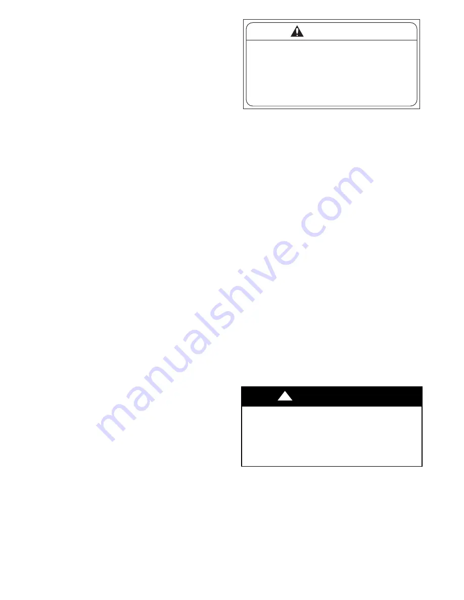
IMPORTANT
: Locate caution label stapled to installation
instructions. Attach to right side of plenum or accessory casing
(See Fig. 14).
AIR CONDITIONING COIL BEHIND THIS
PANEL. DO NOT DRILL OR CUT PANEL
UNTIL COIL LOCATION HAS BEEN
VERIFIED BY REMOVING ACCESS
COVER.
CAUTION
A06285
Fig. 14
−
Plenum Caution Label
NOTE
: The uncased N
−
coil features an enclosure to direct airflow
through the third coil slab.
NOTE
: If coil is not being installed in the standard orientation
(front of coil matching front of furnace) then coil must be raised
2
−
1/4 in. above furnace.
NOTE
: Installing coils rotated 90
_
from the front of the furnace,
in upflow or downflow applications, can cause water blow
−
off or
coil freeze
−
up due to the concentration of air on one slab of the coil
or lack of air to a slab in the coil. It is recommended that on this
type of application, a field
−
supplied adapter be placed between the
coil and furnace to allow air to distribute properly between all slabs
of the coil.
Procedure 4 — Refrigerant Line Connections
Use accessory tubing package or field
−
supplied tubing of
refrigerant grade. Suction tube must be insulated. Do not use
damaged, dirty, or contaminated tubing because it may plug
refrigerant flow
−
control device. ALWAYS evacuate the coil and
field
−
supplied tubing before opening outdoor unit service valves.
Procedure 5 — Connect Refrigerant Liquid and
Suction Lines
SUCTION LINE
Suction line is designed for field sweat connection. Line is plugged
to keep out moisture and dirt. Remove these plugs only when
ready to make connection.
See Table 1 and 2 for coil connection tube size.
For matched and mismatched systems, use line sizes recommended
in outdoor unit Installation Instructions.
UNIT OR PROPERTY DAMAGE HAZARD
Failure to follow this caution may result in property damage.
Take precautions to ensure aluminum tubes do not come in
direct contact or allow for condensate run
−
off with a dissimilar
metal. Dissimilar metals can cause galvanic corrosion and
possible premature failure.
CAUTION
!
The coil can be connected to outdoor units using field
−
supplied
tubing of refrigerant grade. Always evacuate tubing and reclaim
refrigerant when making connections or flaring tubing. Leak check
connections before insulating entire suction line.
1. Remove cabinet access door.
2. Remove rubber plugs, suction plug then liquid plug, from
coil stubs using a pulling and twisting motion. Hold coil
stubs steady to avoid bending or distorting.
3. Remove tubing plate with rubber grommets and slide plate
with grommets onto the refrigerant lines (field line
−
set),
away from braze joints.


