


6
A hot water boiler installed above radiation level must be
equipped with a low water cut off device. A periodic inspection is
necessary, as is flushing of float type devices, per low water cut
off manufacturer’s specific instructions.
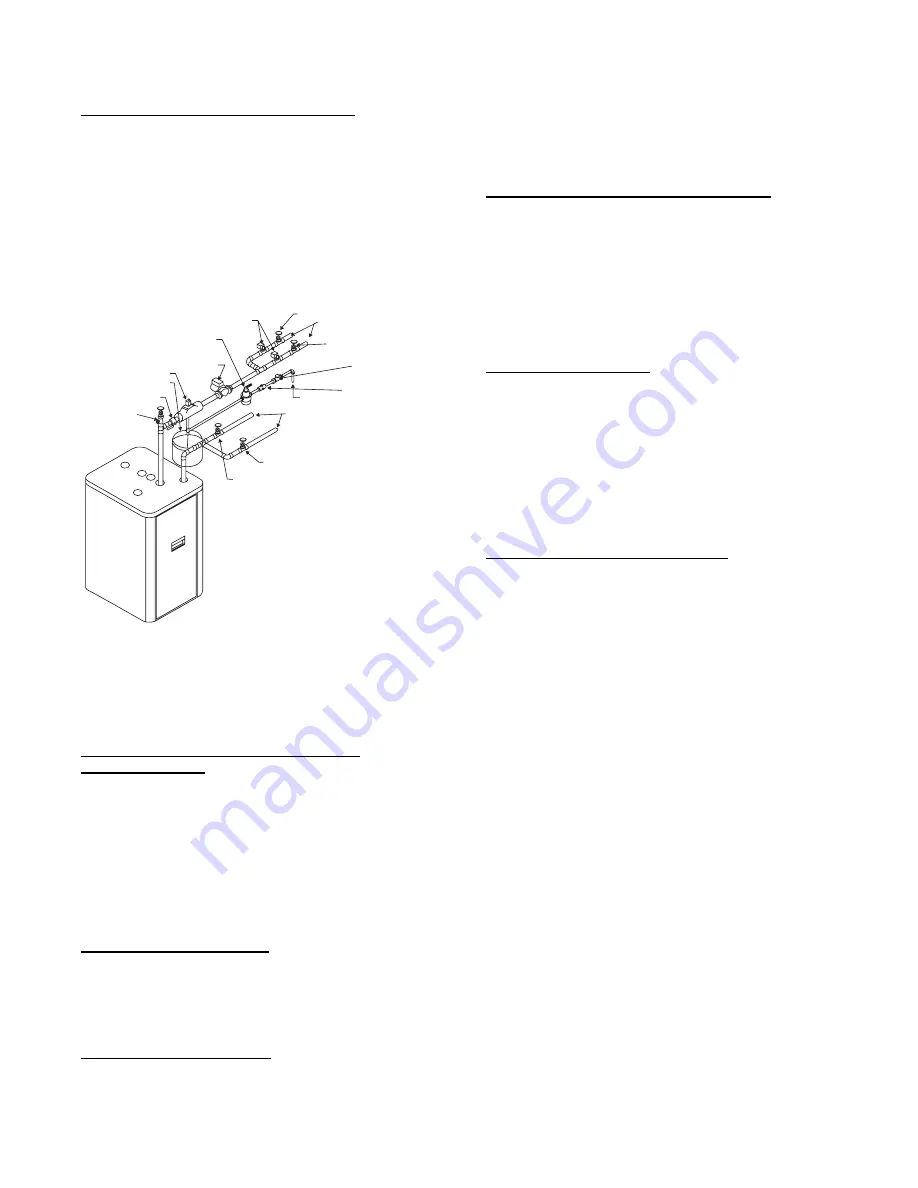
EXPANSION TANK AND MAKE--UP WATER
Determine required system fill pressure, system design
temperature, and system water content. Boiler contains 2.6
gallons (U.S.) Size expansion tank accordingly. Consult
expansion tank manufacturer for proper sizing information.
Connect properly sized expansion tank (not furnished) as shown
in Fig. 6 for diaphragm type expansion tank. For diaphragm type
expansion tanks, adjust the tank air pressure to match the system
fill pressure. Install air vent (furnished) as shown for diaphragm
type expansion tank system only. Install make--up water
connections as shown and per local codes. If a pressure reducing
valve is used, adjust to match the system fill pressure.
ZONE SERVICE
VALVE
REDUCED PRESSURE
BACKFLOW PREVENTER
ZONE SERVICE
VALVE
ZONE SERVICE
VALVE
RETURN FROM
ZONES
FEED
WATER
GATE VALVE
ZONE SERVICE
VALVE
SUPPLY TO
ZONES
ZONE VALVE
PRESSURE
REDUCING VALVE
CIRCULATOR
CAN VENT
EXPANSION TANK
SHUT OFF VALVE
PURGE VALVE
A04051
Fig. 3
---
Multizone Boiler Piping with Zone Valves
In connecting the cold make--up water supply to the boiler, make
sure that clean water supply is available. When the water supply
is from a well or pump, a sand strainer should be installed at the
pump.
PRESSURE RELIEF VALVE/TEMPERATURE
PRESSURE GAUGE
The boiler is furnished with a relief valve and temperature
pressure gauge in the boiler parts bag. Provide 3/4” piping from
the supplied relief valve to a local floor drain, but leave an air gap
between piping and drain. Install the relief valve as shown in Fig.
5. No shutoff of any description shall be placed between safety
relief valve and the boiler, or on the discharge pipes between such
safety valve and the atmosphere. Installation of the safety relief
valve shall conform to ANSI/ASME Boiler and Pressure Vessel
Code, Section IV. The manufacturer is not responsible for any
water damage.
SUPPLY AND RETURN LINES
The packaged boiler unit is set up to receive 1--1/4” NPT supply
and return piping from top access.
NOTE
: The circulator pump is furnished within a carton inside
the boiler cabinet and can be installed at the installer preferred
location.
CONDENSATE DRAIN PIPING
The condensate trap is to be field installed as shown in Fig. 7.
The 1/2” PVC condensate drain fittings are provided in the loose
parts bag. Condensate drain to be pitched down to floor drain at a
minimum of 1/4” per foot.
The 1/2” diameter schedule 40 PVC or CPVC condensate drain
piping and pipe fittings must conform to ANSI standards and
ASTM D1785 or D2846. Schedule 40 PVC or CPVC cement
and primer must conform to ASTM D2564 or F493. In Canada,
use CSA or ULC certified schedule 40 PVC or CPVC drain pipe
and cement.
A condensate pump with a reservoir (not furnished) may be used
to remove condensate to a drain line (sanitary line) above boiler if
a floor drain is not available or is inaccessible.
FILLING CONDENSATE TRAP WITH WATER
NOTE
: On the initial start up, the condensate trap must be
manually filled with water.
The following are the steps required to initially fill the condensate
trap for start up. These steps are only required at the initial start
up or if maintenance requires draining of the condensate trap:
1. Pour about 1 cup of cold tap water into the vent drain line.
2. Excess water should go through the overflow and out
through the condensate drain line. Verify proper operation
of the drain line (or external condensate pump if used).
CHILLED WATER PIPING
The boiler, when used in connection with a refrigeration system,
must be installed so the chiller medium is piped in parallel with
the boiler with appropriate valves to prevent the chilled medium
from entering the boiler.
The boiler piping system of a hot water boiler connected to
heating coils is located in air handling units, where they may be
exposed to refrigerated air circulation, must be equipped with
flow control valves or other automatic means to prevent gravity
circulation of the boiler water during cooling cycle.
STEP 5
—
Combustion Air and Vent Pipe
CONNECTIONS AND TERMINATIONS
For boilers connected to gas vents or chimneys, vent installations
shall be in accordance with part 7, Venting of Equipment, of the
National Fuel Gas Code NFPA 54--2002/ANSI Z223.1--2002,
CSA--B149.1 and B149.2, and applicable provisions of the local
building codes.
Provisions for combustion and ventilation air must be in
accordance with section 5.3, Air For Combustion and Ventilation,
of the National Fuel Gas Code NFPA 54--2002/ANSI
Z223.1--2002, CSA--B149.1 and B149.2, or applicable
provisions of the local building code.
These boilers require a dedicated direct vent system. All air for
combustion is taken directly from outdoors through the
combustion air intake pipe. All flue products are discharged to
the outdoors through the vent pipe.
1. See Fig. 8 through 12 for combustion air and vent pipe
roof and sidewall termination (Roof termination is
preferred). Combustion air and vent pipes must terminate
together in same atmospheric pressure zone as shown.
Construction through which vent and air intake pipes may
be installed is a maximum 24 inches, minimum 1/4”
thickness.
2. Combustion air and vent pipe fittings must conform to
American National Standards Institute (ANSI) standards
and American Society for Testing and Materials (ASTM)
standards
D1784
(schedule--40
CPVC),
D1785
(schedule--40 PVC), D2665 (PVC--DWV), D2241
(SDR--21 and SDR--26 PVC), D2661 (ABS--DWV), or
F628 (schedule--40 ABS). Pipe cement and primer must
conform to ASTM standards D2564 (PVC) or D2235
(ABS).
In Canada construct all combustion air and vent pipes for
this unit of CSA or ULC certified schedule--40 CPVC,
schedule--40 PVC, PVC--DWV or ABS--DWV pipe and
pipe cement. SDR pipe is NOT approved in Canada.


