


13
GROUND-LOOP APPLICATIONS
Temperatures between 20 and 110°F and a cooling capacity of
2.25 to 3 gpm of flow per ton is recommended. In addition to com
-
plying with any applicable codes, consider the following for sys
-
tem piping:
• Limit piping materials to only polyethylene fusion in the
buried sections of the loop.
• Do not use galvanized or steel fittings at any time due to
corrosion.
• Avoid all plastic to metal threaded fittings due to the po
-
tential to leak. Use a flange fitted substitute.
• Do not overtighten connections.
• Route piping to avoid service access areas to unit.
• Use pressure-temperature (P/T) plugs to measure flow of
pressure drop.
INSTALLATION OF SUPPLY AND RETURN HOSE KIT
Follow these piping guidelines.
1. Install a drain valve at the base of each supply and return riser
to facilitate system flushing.
2. Install shutoff/balancing valves and unions at each unit to
permit unit removal for servicing.
3. Place strainers at the inlet of each system circulating pump.
4. Select the proper hose length to allow slack between con
-
nection points. Hoses may vary in length by +2% to –4%
under pressure.
5. Refer to Table 3. Do not exceed the minimum bend radius
for the hose selected. Exceeding the minimum bend radius
may cause the hose to collapse, which reduces water flow
rate. Install an angle adapter to avoid sharp bends in the
hose when the radius falls below the required minimum.
NOTE: Piping must comply with all applicable codes.
Insulation is not required on loop water piping except where the
piping runs through unheated areas or outside the building or
when the loop water temperature is below the minimum expected
dew point of the pipe ambient. Insulation is required if loop water
temperature drops below the dew point.
Pipe joint compound is not necessary when Teflon
1
threaded tape
is pre-applied to hose assemblies or when flared-end connections
are used. If pipe joint compound is preferred, use compound only
in small amounts on the male pipe threads of the fitting adapters.
Prevent sealant from reaching the flared surfaces of the joint.
NOTE: When antifreeze is used in the loop, ensure that it is com
-
patible with Teflon tape or pipe joint compound employed.
Maximum allowable torque for brass fittings is 30 ft-lb. If a torque
wrench is not available, tighten finger-tight plus one quarter turn.
Tighten steel fittings as necessary.
Optional pressure-rated hose assemblies designed specifically
for use with Carrier units are available. Similar hoses can be ob
-
tained from alternate suppliers. Supply and return hoses are fit
-
ted with swivel-joint fittings at one end to prevent kinking
during installation.
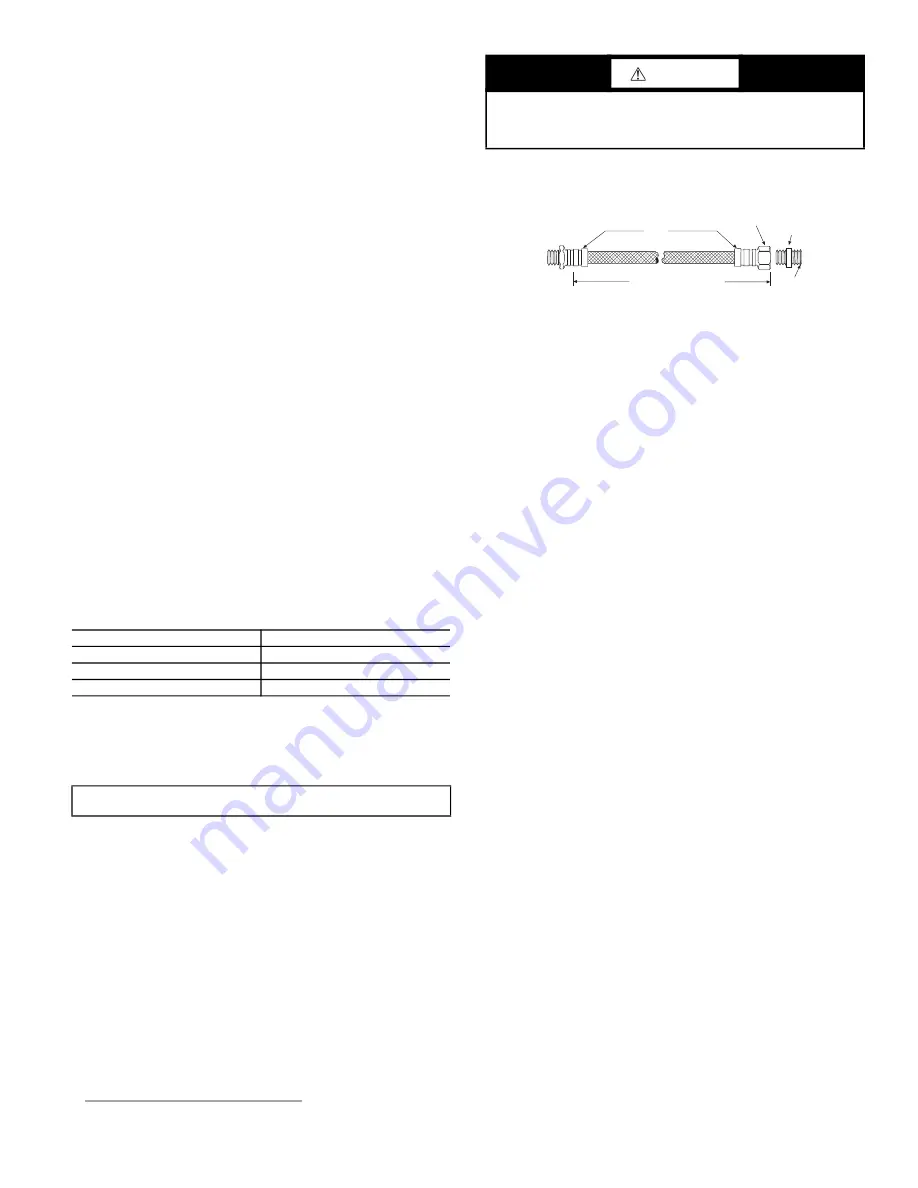
Male adapters secure hose assemblies to the unit and risers. Install
hose assemblies properly and check them regularly to avoid sys
-
tem failure and reduced service life. See Fig. 11.
Fig. 11 —
Supply/Return Hose Kit
AQUASTAT BULB INSTALLATION
Units with Complete C or Deluxe D controls and waterside econo
-
mizer or units with Boilerless Heat Control (all Deluxe D) include
an aquastat with remote sensing bulb that must be field installed
on the incoming water piping. The remote sensing bulb must be
installed on a straight section of uninsulated pipe that provides a
good measurement of the entering water temperature. It is recom
-
mended to insulate the sensing bulb after installation for better wa
-
ter temperature sensing.
INSTALLATION OF HOT WATER GENERATOR OPTION
The hot water generator (HWG) is a factory-installed option capa
-
ble of providing hot water in the range of 110 to 140°F as a sup
-
plemental domestic hot water source. The HWG is a desuper
-
heater that uses recovered heat from the hot discharge gas leaving
the compressor. Included with the HWG is a vented, double wall
coil, circulating pump, high water temperature limit switch (set at
140°F), discharge gas temperature limit switch, and an ON/OFF
switch with built-in circuit breaker. The generator operates inde
-
pendently and is not factory wired to the unit controller.
NOTE: The HWG will reduce the amount of heat available to the
space and it is recommended to deactivate the HWG in heating
mode via the ON/OFF switch.
Water Tank Preparation
1. Turn off electrical or fuel supply to the water heater.
2. Attach garden hose to water tank drain connection and run
other end of hose outdoors or to an open drain.
3. Close cold water inlet valve to water heater tank.
4. Drain tank by opening drain valve on the bottom of the tank,
then open pressure relief valve or hot water faucet.
5. Once drained the tank should be flushed with cold water until
the water leaving the drain hose is clear and free of sediment.
6. Close all valves and remove the drain hose.
7. Install HWG water piping.
All hot water piping should be a minimum of 3/8 in. OD copper
tube to a maximum distance of fifteen feet. For distances beyond
fifteen feet but not exceeding sixty feet use 1/2 in. copper tube.
Separately insulate all exposed surface of both connecting water
lines with 3/8 in. wall closed cell insulation. Install isolation
valves on supply and return to the hot water generator. See Fig. 12.
NOTE: Diagram is for illustration purposes only. Ensure access to
heat pump is not restricted. All plumbing and piping connections
must comply with local plumbing codes.
Table 3 —
Metal Hose Minimum Bend Radii
HOSE DIAMETER (in.)
MINIMUM BEND RADII (in.)
1/2
2-1/2
3/4
4
1
5-1/2
IMPORTANT: Do not bend or kink supply lines or hoses.
1.
Teflon is a registered trademarks of DuPont.
CAUTION
Backup wrench is required when tightening water connections
to prevent water line damage. Failure to use a backup wrench
could result in equipment damage.
Rib
Crimped
Length
(2 Ft Length Standard)
Swivel
Brass
Fitting
Brass
Fitting
MPT
Summary of Contents for AQUAZONE 50PSH
Page 17: ...17 Fig 15 PSC Motor Single Phase Single Stage WSHP Open Control ...
Page 20: ...20 Fig 18 Constant Torque Motor Single Phase Single Stage WSHP Open Control ...
Page 23: ...23 Fig 21 Constant Airflow Single Phase WSHP Open ...
Page 26: ...26 Fig 24 PSC Motor Three Phase Single Stage WSHP Open ...
Page 29: ...29 Fig 27 Constant Torque Motor Three Phase Single Stage WSHP Open ...
Page 32: ...32 Fig 30 Constant Airflow Motor Three Phase Single Stage WSHP Open ...


