


11
4. Select the proper hose length to allow slack between connec-
tion points. Hoses may vary in length by +2% to –4% under
pressure.
5. Do not exceed the minimum bend radius for the hose
selected. Refer to Table 3. Exceeding the minimum bend
radius may cause the hose to collapse, which reduces water
flow rate. Install an angle adapter to avoid sharp bends in the
hose when the radius falls below the required minimum.
NOTE: Piping must comply with all applicable codes.
Insulation is not required on loop water piping except where the
piping runs through unheated areas or outside the building or
when the loop water temperature is below the minimum expected
dew point of the pipe ambient. Insulation is required if loop water
temperature drops below the dew point.
UNITS WITH WATERSIDE ECONOMIZER OR BOILER-
LESS HEAT CONTROL
Units with Complete C or Deluxe D controls and waterside econo-
mizer or units with boilerless heat control (Deluxe D Only) in-
clude an aquastat with remote.
Pipe joint compound is not necessary when Teflon
1
threaded tape
is pre-applied to hose assemblies or when flared-end connections
are used. If pipe joint compound is preferred, use compound only
in small amounts on the male pipe threads of the fitting adapters.
Prevent sealant from reaching the flared surfaces of the joint.
NOTE: When anti-freeze is used in the loop, assure that it is com-
patible with Teflon tape or pipe joint compound employed.
Maximum allowable torque for brass fittings is 30 ft-lb. If a torque
wrench is not available, tighten finger-tight plus one quarter turn.
Tighten steel fittings as necessary.
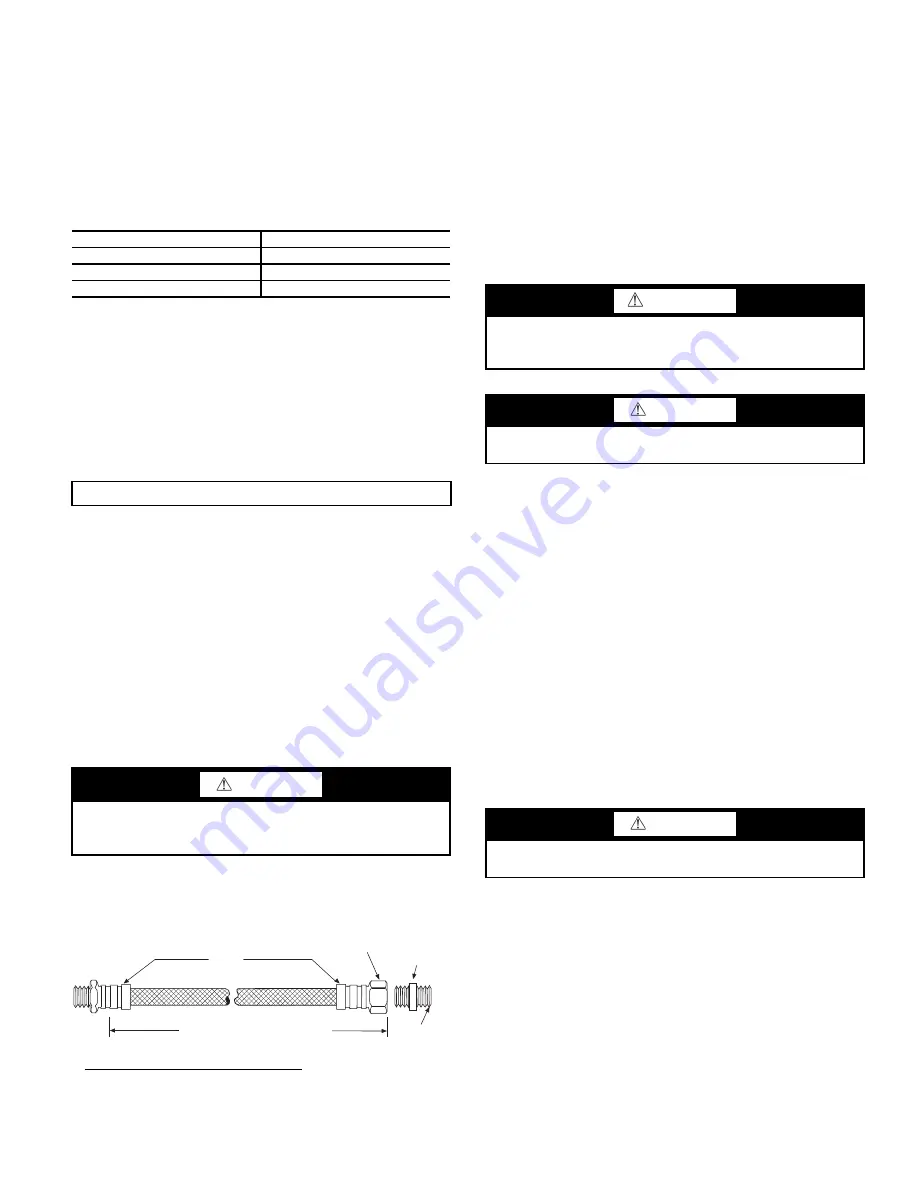
Optional pressure-rated hose assemblies designed specifically
for use with Carrier units are available. Similar hoses can be ob-
tained from alternate suppliers. Supply and return hoses are fit-
ted with swivel-joint fittings at one end to prevent kinking
during installation.
Male adapters secure hose assemblies to the unit and risers. Install
hose assemblies properly and check them regularly to avoid sys-
tem failure and reduced service life. See Fig. 10.
Fig. 10 — Supply/Return Hose Kit
AQUASTAT BULB INSTALLATION
Units with Complete C or Deluxe D controls and waterside econo-
mizer or units with Boilerless Heat Control (all Deluxe D) include
an aquastat with remote sensing bulb that must be field installed
on the incoming water piping. The remote sensing bulb must be
installed on a straight section of uninsulated pipe that provides a
good measurement of the entering water temperature. It is recom-
mended to insulate the sensing bulb after installation for better wa-
ter temperature sensing.
Step 8 — Wire Field Power Supply
See Fig. 11-18 for typical wiring diagrams. See Tables 4 and 5 for
additional electrical data. Please refer to the unit wiring diagram
attached to the control panel for field installation.
HIGH VOLTAGE
All field-installed wiring must comply with the National Electric
Code as well as all applicable local codes. Refer to the unit electri-
cal data on the unit nameplate for wire and branch circuit protec-
tion sizing. Supply power voltage and phasing should match the
required voltage and phasing shown on the unit nameplate. Oper-
ating the unit below the minimum voltage, above the maximum
voltage or with incorrect phasing can result in poor system perfor-
mance or damage to the heat pump. All field wiring should be in-
stalled by qualified and trained personnel. Refer to the unit wiring
diagram for field connection requirements.
Power wiring to the heat pump should be enclosed in flexible con-
duit to minimize the transmission of vibration from the unit cabi-
net to the building.
For heat pumps with unit mounted disconnect switches, field pow-
er should be connected to the marked terminals on the disconnect
switch. For heat pumps without unit-mounted disconnect switches
(except units with dual power supply), power is connected to the
line (L) side of the compressor contactor and the ground lug in the
unit electrical box.
Transformer Settings for 208/230-v Units
As factory built, all 208/230-v units are wired for 230-v operation.
For jobsites with a 208-v power supply, the primary leads on the
unit transformer will need to be changed from 230-v to 208-v. Re-
fer to the unit wiring diagram for details.
Table 3 — Metal Hose Minimum Bend Radii
HOSE DIAMETER (in.)
MINIMUM BEND RADII (in.)
1
/
2
2
1
/
2
3
/
4
4
1
5
1
/
2
IMPORTANT: Do not bend or kink supply lines or hoses.
1. Teflon is a registered trademark of DuPont.
CAUTION
Backup wrench is required when tightening water connections
to prevent water line damage. Failure to use a backup wrench
could result in equipment damage.
RIB
CRIMPED
LENGTH
(2 ft LENGTH
S
TANDARD)
S
WIVEL
BRA
SS
FITTING
BRA
SS
FITTING
MPT
WARNING
To avoid possible injury or death due to electrical shock, open
the power supply disconnect switch and secure it in an open
position during installation.
CAUTION
All power connections must be properly torqued to avoid the
risk of overheating.
CAUTION
The power supply ground wire should never be used as a neu-
tral wire.