background image

INSTALLATION,  OPERATION AND 

M A I N T E N A N C E   I N S T R U C T I O N S

Original document

Reversible Air-to-Water Heat Pumps

30RQS/30RQSY 039-160 “B”

For the operation of the control please refer to the

Touch Pilot Junior Control manual for the 30RBS/RQS 039-160 series

Nominal cooling capacity 30RQS 38-148 kW - 50 Hz

Nominal heating capacity 30RQS 42-150 kW - 50Hz

Nominal cooling capacity 30RQSY 37-146 kW - 50 Hz

Nominal heating capacity 30RQSY 42-151 kW - 50Hz

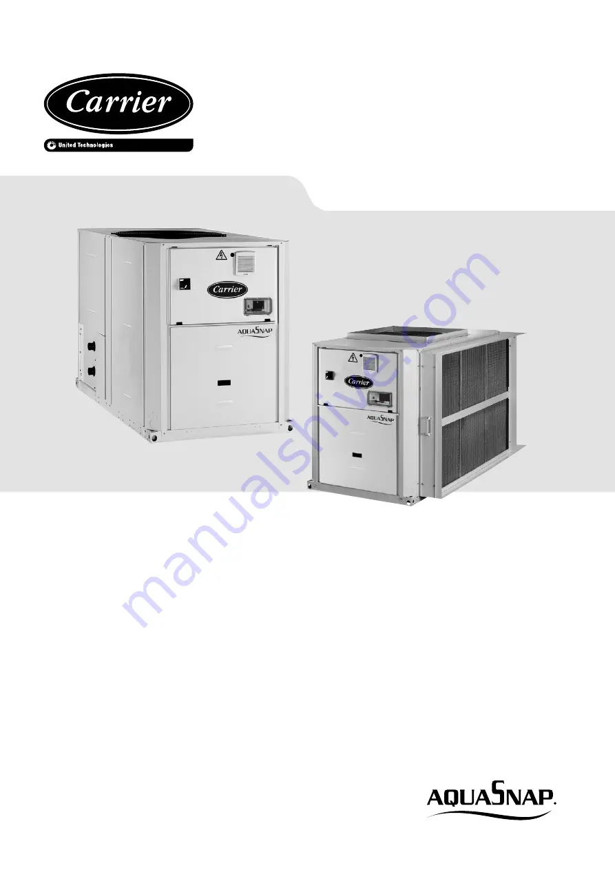
30RQS

30RQSY

Touch Pilot Junior

Summary of Contents for AquaSnap Touch Pilot Junior 30RQS

Page 1: ...160 B For the operation of the control please refer to the Touch Pilot Junior Control manual for the 30RBS RQS 039 160 series Nominal cooling capacity 30RQS 38 148 kW 50 Hz Nominal heating capacity 30RQS 42 150 kW 50Hz Nominal cooling capacity 30RQSY 37 146 kW 50 Hz Nominal heating capacity 30RQSY 42 151 kW 50Hz 30RQS 30RQSY Touch Pilot Junior ...

Page 2: ... module with filter frame 17 4 7 30RQSY 080 120 units with and without hydraulic module 18 4 8 30RQSY 140 160 units with and without hydraulic module 19 4 9 30RQS RQSY 039 078 units with buffer tank module 20 4 10 30RQS RQSY 080 160 units with buffer tank module 21 4 11 30QBS RQSY 039 080 units with desuperheater 22 4 12 30RQS RQSY 090 120 units with desuperheater 22 4 13 30RQS RQSY 140 160 units ...

Page 3: ...45 15 10 High pressure safety switch 45 15 11 Storage tank 45 15 12 Four way valve 45 15 13 Control box 45 16 OPTIONS 46 17 SPECIFIC DETAILS FOR UNITS WITH A FAN WITH AVAILABLE STATIC PRESSURE 30RQSY 48 18 PARTIAL HEAT RECLAIM USING DESUPER HEATERS OPTION 49 49 18 1 Physical data 30RQS 30RQSY units with partial heat reclaim using desuperheaters option 49 49 18 2 Installation and operation of the h...

Page 4: ...he system ductwork In the heating mode the full load or part load speed of each circuit is fixed and at the configured maximum range configurable from 12 r s to 19 r s based on the constraints and characteristics of the installation site The maximum configured speed applies to both the heating and cooling mode If required and for reasons that may apply at the installation site of the 30RQSY units ...

Page 5: ...pleting the hydraulic installation Do not remove these valves and fuses even if the fire risk is under control for a particular installation There is no guarantee that the accessories are re installed if the installation is changed or for transport with a gas charge When the unit is subjected to fire safety devices prevent rupture due to over pressure by releasing the refrigerant The fluid may the...

Page 6: ...mmend to follow the instructions in EN 378 3 2 Performed in the presence of A1 refrigerant according to EN 378 1 Never work on a unit that is still energized Never work on any of the electrical components until the general power supply to the unit has been cut If any maintenance operations are carried out on the unit lock the power supply circuit in the open position and secure the machine upstrea...

Page 7: ...e personnel in charge to avoid deterioration and injury Faults and leaks must be repaired immediately The authorized technician must have the responsibility to repair the fault immediately After each unit repair check the operation of the protection devices and create a 100 parameter operation report Comply with the regulations and recommendations in unit and HVAC installation safety standards suc...

Page 8: ...pping or losing your balance Use only original replacement parts for any repair or component replacement Consult the list of replacement parts that corresponds to the specification of the original equipment Do not drain water circuits containing industrial brines without informing the technical service department at the installation site or a competent body first Close the entering and leaving wat...

Page 9: ...peration If 30RQS RQSY units are hoisted with rigging it is advisable to protect coils against crushing while a unit is being moved Use struts or a lifting beam to spread the slings above the unit Do not tilt a unit more than 15 WARNING Never push or lever on any of the enclosure panels of the unit Only the base of the unit frame is designed to withstand such stresses 2 3 Checks before system star...

Page 10: ...Y 039 to 078 units Fan discharge side at the evacuation side of the treated air by the unit heat exchanger 30RQSY 039 to 160 For the precise dimensions of this connection interface please refer to the dimensional drawings for the units Location of the air temperature sensor 3 2 1 Standard unit suction connection 30RQSY 039 to 078 units are supplied with a sleeve that allows connection of an air he...

Page 11: ...red by the variable speed controller in case of a locked rotor or overload If a fan des not operate the variable speed controller will automatically detect this and an alert will be sent to the Touch Pilot Junior display For the specific alarms list of this option please refer to the 30RB RQ Touch Pilot Junior control manual 3 4 Air heat exchanger suction filter kit option 23b This option is avail...

Page 12: ...available on request when designing an installation For the location of fixing points weight distribution and coordinates of the centre of gravity refer to the certified dimensional drawings B In multiple unit installations maximum four units the side clearance between the units should be increased from 1000 to 2000 mm C The height of the solid surface must not exceed 2 m Control box Water inlet W...

Page 13: ...tion of fixing points weight distribution and coordinates of the centre of gravity refer to the certified dimensional drawings B In multiple unit installations maximum four units the side clearance between the units should be increased from 1000 to 2000 mm C The height of the solid surface must not exceed 2 m Control box Water inlet Water outlet B Required clearances for air flow C Recommended cle...

Page 14: ... available on request when designing an installation For the location of fixing points weight distribution and coordinates of the centre of gravity refer to the certified dimensional drawings B Provide a gutter around the unit to collect the condensate water or install the accessory condensate collection pan 30RQSY 039 to 078 C The unit must be installed level less than 2 mm per metre deviation in...

Page 15: ...t or available on request when designing an installation For the location of fixing points weight distribution and coordinates of the centre of gravity refer to the certified dimensional drawings B Provide a gutter around the unit to collect the condensate water or install the accessory condensate collection pan 30RQSY 039 to 078 C The unit must be installed level less than 2 mm per metre deviatio...

Page 16: ...r available on request when designing an installation For the location of fixing points weight distribution and coordinates of the centre of gravity refer to the certified dimensional drawings B Provide a gutter around the unit to collect the condensate water or install the accessory condensate collection pan 30RQSY 039 to 078 C The unit must be installed level less than 2 mm per metre deviation i...

Page 17: ...t or available on request when designing an installation For the location of fixing points weight distribution and coordinates of the centre of gravity refer to the certified dimensional drawings B Provide a gutter around the unit to collect the condensate water or install the accessory condensate collection pan 30RQSY 039 to 080 C The unit must be installed level less than 2 mm per metre deviatio...

Page 18: ...ct Power cable entry NOTES A Non certified drawings Refer to the certified dimensional drawings supplied with the unit or available on request when designing an installation For the location of fixing points weight distribution and coordinates of the centre of gravity refer to the certified dimensional drawings B The unit must be installed level less than 2 mm per metre deviation in both axes Over...

Page 19: ...try NOTES A Non certified drawings Refer to the certified dimensional drawings supplied with the unit or available on request when designing an installation For the location of fixing points weight distribution and coordinates of the centre of gravity refer to the certified dimensional drawings B The unit must be installed level less than 2 mm per metre deviation in both axes Overall dimensions 4 ...

Page 20: ...For the location of fixing points weight distribution and coordinates of the centre of gravity refer to the certified dimensional drawings B The unit must be installed level less than 2 mm per metre deviation in both axes Overall dimensions RQSY RQSY 050 060 070 078 Control box Water inlet Water outlet B Required clearances for air flow C Recommended clearances for maintenance Air outlet do not ob...

Page 21: ...nstallation For the location of fixing points weight distribution and coordinates of the centre of gravity refer to the certified dimensional drawings B The unit must be installed level less than 2 mm per metre deviation in both axes Overall dimensions RQSY Control box Water inlet Water outlet B Required clearances for air flow C Recommended clearances for maintenance Air outlet do not obstruct Po...

Page 22: ...SY 090 120 units with desuperheater Position of the desuperheater inlets and outlets 4 13 30RQS RQSY 140 160 units with desuperheater Position of the desuperheater inlets and outlets Unit with grille protection option B Unit water inlet and outlet C Water inlet and outlet unit with option 49 4 DIMENSIONS CLEARANCES ...

Page 23: ... Maximum total air flow l s 3692 3690 3910 5285 5284 5282 7770 7380 7376 7818 10568 10568 Maximum rotation speed r s 12 12 12 16 16 16 12 12 12 12 16 16 Water heat exchanger Direct expansion plate heat exchanger Water volume l 2 6 3 0 4 0 4 8 4 8 5 6 8 7 8 7 9 9 11 3 12 4 14 7 Without hydraulic module Max water side operating pressure kPa 1000 1000 1000 1000 1000 1000 1000 1000 1000 1000 1000 1000...

Page 24: ...raw 3 A 26 29 33 36 42 53 53 55 62 77 85 106 Maximum unit current draw Un 4 A 35 45 47 53 67 73 74 81 99 108 134 146 Maximum unit current draw Un 10 A 38 49 51 58 75 80 80 89 110 118 150 159 Customer side unit power reserve kW Customer reserve at the 24 V control power circuit Short circuit stability and protection See table 9 1 1 Maximum instantaneous start up current at operating limit values ma...

Page 25: ... with rotating shroud Quantity 1 1 1 1 1 1 2 2 2 2 2 2 Maximum total air flow l s 3692 3690 3910 5278 4982 5267 7770 7380 7376 7818 9964 10534 Maximum speed r s 16 16 16 18 18 18 16 16 16 16 18 18 Water heat exchanger direct expansion type Plate heat exchanger max water side operating pressure without hydraulic module 1000 kPa Water volume l 2 6 3 0 4 0 4 8 4 8 5 6 8 7 8 7 9 9 11 3 12 4 14 7 With ...

Page 26: ...ximum unit current draw Un 4 A 37 47 49 55 67 73 79 86 104 113 135 147 Maximum unit current draw Un 10 A 41 52 54 61 75 80 85 94 116 123 150 160 Customer side unit power reserve kW Customer reserve at the 24 V control power circuit Short circuit stability and protection See table 9 1 1 Maximum instantaneous start up current at operating limit values maximum operating current of the smallest compre...

Page 27: ... This information varies depending on the manufacturer and model at the time of incorporation Please refer to the motor name plates 4 Manufacturer s name and trademark commercial registration number and place of manufacturer 5 Product s model number 6 Number of motor poles 2 2 2 2 2 2 2 2 2 2 2 2 7 1 Rated shaft power output at full load and nominal voltage 400 V kW 0 8 0 8 0 8 0 8 0 8 0 8 0 8 0 8...

Page 28: ...itudes above sea level m 1000 II Ambient air temperature C 55 IV Maximum air temperature C Please refer to the operating conditions given in this manual or in the specific conditions in the Carrier selection programs V Potentially explosive atmospheres Non ATEX environment 1 Required by regulation 640 2009 with regard to the application of directive 2009 125 EC on the eco design requirements for e...

Page 29: ...48 C class 4K4H altitude 2000 m see note for table 9 2 Electrical data hydraulic module presence of hard solids class 4S2 no significant dust present presence of corrosive and polluting substances class 4C2 negligible 2 Power supply frequency variation 2 Hz 3 The neutral N conductor must not be connected directly to the unit if necessary use a transformer 4 Overcurrent protection of the power supp...

Page 30: ... 070 and 078 and 140 160 and up to 240 Pa for all other sizes 10 2 Operating range standard units heating mode Condenser Minimum Maximum Entering water temperature at start up C 8 45 Leaving water temperature during operation C 25 55 Entering leaving water temperature difference K 3 10 Evaporator Minimum Maximum Air temperature C 15 40 Hydraulic module 1 Entering air temperature Kit without pump C...

Page 31: ... This tank should be equipped with baffles to allow mixing of the fluid water or brine Please refer to the examples below For the Buffer Tank Module option the tank volume must be taken into account 250 litres Bad Good Bad Good 10 6 2 Maximum water loop volume Units with hydraulic module incorporate an expansion tank that limits the water loop volume The table below gives the maximum loop volume f...

Page 32: ...mum machine cur rent see electrical data tables and standard installation practises in accordance with IEC 60364 table 52C have been applied 30RQS units are installed outside No 17 suspended aerial lines No 61 buried conduit with a derating coefficient of 20 The calculation is based on PVC or XLPE insulated cables with copper core A maximum ambient temperature of 46 C has been taken into considera...

Page 33: ...am supplied with the unit for the field control wiring of the following features Water heat exchanger pump interlock mandatory Remote on off switch Demand limit external switch Remote dual set point Alarm alert and operation report Heating cooling selection 11 6 Power supply ATTENTION After the unit has been commissioned the power supply must only be disconnected for quick maintenance operations o...

Page 34: ...er inlet and outlet connections shown on the unit Install manual or automatic air purge valves at all high points in the circuit Use a pressure reducer to maintain pressure in the circuit s and install a relief valve as well as an expansion tank Units with the hydraulic module include a relief valve and an expansion tank Install thermometers in both the entering and leaving water connections Insta...

Page 35: ...ust comply with basic regulations especially for minimum and maximum flow rates which must be between the values listed in the operating limit table application data To prevent corrosion by differential aeration the complete drained heat transfer circuit must be charged with nitrogen for a period of one month If the heat transfer fluid does not comply with the Carrier regu lations the nitrogen cha...

Page 36: ...ionmanual 11 Check valve If dual pump 12 Plate heat exchanger 13 Heater or tracer for frost protection Option 14 Flow sensor for water heat exchange 15 Buffer tank module option Installation components 16 Thermowell 17 Air purge 18 Flexible connexion 19 Shut off valve 20 Screen filter obligatory for a unit without hydraulic module 21 Pressure gauge 22 Water flow control valve Note Not necessary fo...

Page 37: ...izes 039 078 Dual pump shown Hydraulic module sizes 080 160 Dual pump shown Hydraulic module sizes 039 080 Dual pump and buffer tank shown Hydraulic module sizes 090 160 Dual pump and buffer tank shown 12 WATER CONNECTIONS ...

Page 38: ...tart up the system pump Read the pressure drop of the plate heat exchanger as the difference between the unit inlet and outlet pressures item 21 Let the pump run for 2 hours consecutively to clean up the hydraulic circuit of the system presence of contaminating solids Perform another reading Compare this value to the initial value A decrease in the pressure drop value indicates that the filters in...

Page 39: ...ow rate or minimum frequency and this results in a higher pressure differential than the set point See with Carrier Service to implement the procedures described below 13 3 1 Procedure for cleaning the hydraulic circuit Before proceeding it is advisable to remove any possible contamination from the hydraulic circuit Start up the system pump by using the forced start command Control the frequency t...

Page 40: ...Set water flow control to temperature differential Set the value of the required differential temperature By default the unit is factory configured at the minimum speed frequency 50 Hz 13 5 Plate heat exchanger pressure drop including internal piping units without hydraulic module 30RQS RQSY 039 078 Pressure drop kPa Water flow rate l s 0 10 20 30 40 50 60 70 80 90 100 110 120 130 140 150 0 0 0 5 ...

Page 41: ...220 0 1 2 3 4 5 6 7 8 9 10 1 2 3 4 5 Available static pressure kPa Water flow rate l s Legend Legend 1 30RQS RQSY 039 4 30RQS RQSY 060 070 1 30RQS RQSY 080 090 4 30RQS RQSY 140 2 30RQS RQSY 045 5 30RQS RQSY 078 2 30RQS RQSY 100 5 30RQS RQSY 160 3 30RQS RQSY 050 3 30RQS RQSY 120 High pressure pumps Available static pressure kPa Water flow rate l s 50 70 90 110 130 150 170 190 210 230 0 1 2 3 4 5 6 ...

Page 42: ...ed 14 3 Operation of two units in master slave mode The control of a master slave assembly is in the entering water and does not require any additional sensors standard configuration It can also be located in the leaving water In this case two additional sensors must be added on the common piping All parameters required for the master slave function must be configured using the Service Configurati...

Page 43: ...oor air temperature This requires only a 400 V 3 ph 50 Hz power supply source as well as a connection to the unit via a communication bus For the required configuration of the stages consult the 30RB RQ Touch Pilot Junior Control IOM Typical accessory installation diagram Legend 1 Electric heater power supply 400 V 3 ph 50 Hz 2 Accessory control board for four additional electric heaters 3 Interna...

Page 44: ...in the circuit The presence of bubbles in the sight glass indicates an insufficient charge or non condensables in the system The presence of moisture changes the colour of the indicator paper in the sight glass 15 7 Filter drier This is a one piece brazed filter drier located in the liquid line The role of the filter drier is to keep the circuit clean and moisture free The moisture indicator shows...

Page 45: ... Monitoring during operation Follow the regulations on monitoring pressurised equipment It is normally required that the user or operator sets up and maintains a monitoring and maintenance file If there are no regulations or to complement them follow the control programmes of EN 378 If they exist follow local professional recommendations Regularly check for possible presence of impurities e g sili...

Page 46: ...operation of two units connected in parrallele operation with operating time equalisation 30RQS RQSY 039 160 Main disconnect switch without fuse 70 Factory installed main electric disconnect switch in the control box Ease of installation and compliance with local electrical regulations 30RQS RQSY 039 160 HP single pump hydraulic module 116R Single high pressure water pump water filter electronic w...

Page 47: ...anagement 156b Control board factory installed on the unit with additional inputs outputs in order to manage up to 4 externals heating stage electrical heaters Extended remote control capabilities to up to 4 electrics heaters Permits easy control of a basic heating system 30RQS RQSY 039 160 Compliance with Russian regulations 199 EAC certification Conformance with Russian regulations 30RQS 039 160...

Page 48: ...RQSY 140 160 Duct pressure drop Fan speed r s Power input coefficient Cooling capacity coefficient 0 15 83 0 929 1 018 50 16 81 0 944 1 016 100 17 78 0 964 1 014 130 18 36 0 978 1 011 160 18 36 1 000 1 000 180 18 36 1 019 0 991 Heating mode 30RQSY 039 050 30RQSY 080 120 Duct pressure drop Fan speed r s Power input coefficient Heating capacity coefficient 0 18 36 0 990 1 016 50 18 36 0 990 1 012 10...

Page 49: ...tank module option kg 958 966 993 1007 1007 1015 1238 1406 1414 1479 1582 1600 Operating weight 30RQSY units with RTPF coils 1 Standard unit without hydraulic module kg 519 526 560 574 574 581 763 931 940 998 1103 1120 Standard unit with hydraulic module option Single high pressure pump kg 549 556 589 603 604 611 793 962 972 1034 1142 1159 Dual high pressure pump kg 575 582 615 629 630 637 918 100...

Page 50: ...tion option in case of a fire relief valve 7 Electric heater to protect the desuperheater against frost not supplied 8 Desuperheater insulation not supplied 9 Unit control box 10 NA 11 Desuperheater water inlet 12 Desuperheater water outlet 13 Evaporator water inlet 14 Evaporator water outlet 15 Unit with desuperheater option without hydraulic module 16 System heat load 17 Border between the 30RQS...

Page 51: ...mperature This temperature is directly linked to the condenser entering air temperature entering air temperature in cooling mode and water temperature in heating mode 18 4 2 Reclaim priority mode In cooling mode only this configuration allows the user to enter a setpoint that is relative to the minimum condensing temperature default 40 C to increase the heating capacity reclaimed at the desuperhea...

Page 52: ... our supplier based on the antifreeze solutions used in the Carrier Montluel laboratory are as follows these values can change for different suppliers by weight glycol Freeze point C ethylene glycol Freeze point C propylene glycol 10 3 8 2 6 15 6 1 4 3 20 8 8 6 6 25 11 8 9 6 30 15 2 13 35 19 1 16 7 40 23 6 20 7 45 29 25 3 Based on the table above if the ethylene glycol concentration by weight in t...

Page 53: ... Check the tightening of the fan tower fan compressor and control box fixing bolts Water circuit checks Always take care when working on the water circuit to ensure that the condenser close by is not damaged Check the water connections Check the expansion tank for signs of excessive corro sion or gas pressure loss and replace it if necessary Purge the water circuit see chapter Water flow control p...

Page 54: ...dustrial installations and near trees that shed their leaves For coil cleaning two maintenance levels are used based on the AFNOR X60 010 standard If the air heat exchangers are fouled clean them gently in a vertical direction using a brush Only work on air heat exchangers with the fans switched off For this type of operation switch off the HVAC unit if service considerations allow this Clean air ...

Page 55: ...3 36 2087 60 3706 11 453 13 1087 37 2142 61 3789 10 473 14 1121 38 2197 62 3874 9 493 15 1156 39 2253 63 3961 8 514 16 1192 40 2311 64 4049 7 535 17 1229 41 2369 65 4138 6 557 18 1267 42 2429 66 4229 5 579 19 1305 43 2490 67 4322 4 602 20 1344 44 2551 68 4416 3 626 21 1384 45 2614 69 4512 2 650 22 1425 46 2678 70 4610 1 674 23 1467 47 2744 0 700 24 1509 48 2810 1 726 26 1596 49 2878 2 752 25 1552 ...

Page 56: ...minals are tight All cables and thermistors have been inspected for crossed wires All plug assemblies are tight Check air handling systems All air handlers are operating All chilled water valves are open All fluid piping is connected properly All air has been vented from the system Chilled water pump is operating with the correct rotation CWP amperage Rated Actual Unit start up Water pump control ...

Page 57: ...The flow rate in l s corresponds to the specification of l s Carry out the QUICK TEST function see RB 30RQ Touch Pilot Junior control manual Check and register the configuration of the follwoing parameters Load sequence selection Capacity ramp loading selection Start up delay Burner section Pump control Set point reset mode Night time capacity setback Re enter the set points see controls section T...

Page 58: ...validity of certificate www eurovent certification com Order No 13465 09 2018 Supersedes order No 13465 01 2017 Manufactured by Carrier SCS Montluel France Manufacturer reserves the right to change any product specifications without notice Printed in the European Union ...

Reviews: