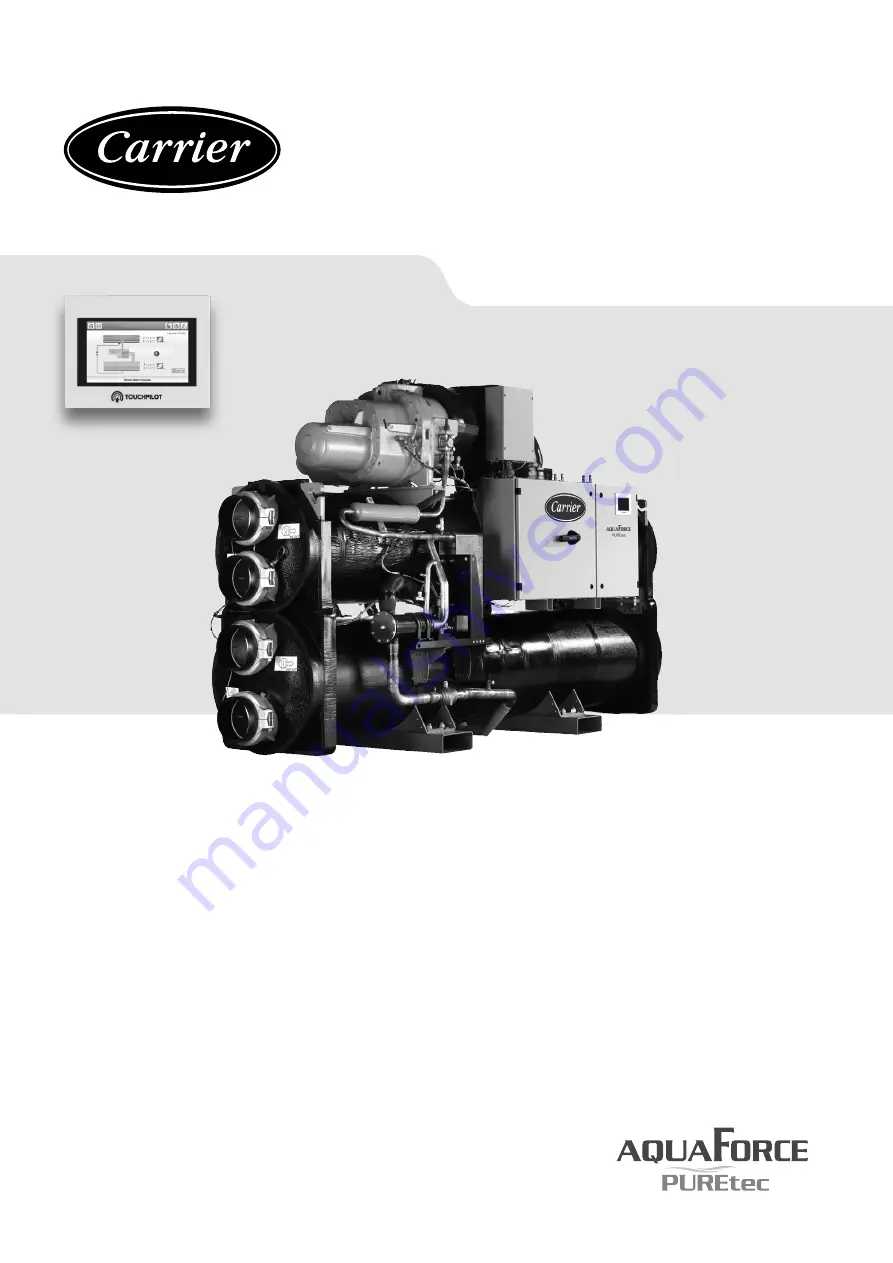
High temperature water-source heat pump
AquaForce
®
PUREtec with R1234ze(E)
61XWHLZE 03 - 17
61XWH-ZE 03 - 17
61XWHHZE 03-10 & 15
I N S T A L L A T I O N , O P E R A T I O N
A N D M A I N T E N A N C E M A N U A L
Original document
Page 1: ...erature water source heat pump AquaForce PUREtec with R1234ze E 61XWHLZE 03 17 61XWH ZE 03 17 61XWHHZE 03 10 15 I N S T A L L A T I O N O P E R A T I O N A N D M A I N T E N A N C E M A N U A L Original document ...
Page 2: ...2 ...
Page 3: ...8 6 1 Operating limits 18 6 2 Minimum chilled water flow 18 6 3 Maximum chilled water flow 18 6 4 Condenser water flow rate 18 6 5 Standard and optional number of water passes 18 6 6 Evaporator and condenser water flow rates 18 6 7 Variable flow evaporator 19 6 8 System minimum water volume 19 6 9 Evaporator pressure drop curves 20 6 10 Condenser pressure drop curves 20 7 WATER CONNECTIONS 21 7 1 ...
Page 4: ...RD MAINTENANCE 27 11 1 Level 1 maintenance 27 11 2 Level 2 maintenance 27 11 3 Level 3 or higher maintenance 27 11 4 Tightening of the electrical connections 28 11 5 Tightening torques for the main bolts and screws 29 11 6 Evaporator and condenser maintenance 29 11 7 Compressor maintenance 29 11 8 Expansion valves maintenance 29 11 9 High pressure safety loop periodic test 30 12 FINAL SHUTDOWN 31 ...
Page 5: ...ance to EN 378 No Charge limitations apply for the level of occupancy is C Please refer to these standards for further details This level needs to be confirmed by the customer Refer also to paragraph 2 for Additional guidelines for safe use of R1234ze E refrigerant in machinery rooms After the unit has been received when it is ready to be installed or reinstalled and before it is started up it mus...
Page 6: ...ns forexample those of European standards EN 378 These standards include a sizing method and examples for configuration and calculation Under certain conditions they permit connection of several valves to the same discharge pipe Carrier recommends using flexible hose to connect the relief valves to discharge pipe Special care shall be taken so that coupling to discharge pipe is not creating mechan...
Page 7: ...on device This valve is situated on the liquid line before the filter drier In case of presence of a shut off valve on the suction line between evaporator and compressor factory option n 92 never close at the same time the shut off valve situated on the discharge line between compressor and condenser One exception can be made in case of compressor removal from the refrigerant circuit As a conseque...
Page 8: ...ernal walls and on non protected steel surfaces 1 4 Repair safety considerations Equip the engineers that work on the unit with the protections described in section 1 3 above It is compulsory to wear personal protection equipment and a detector of explosive atmospheres The insulation must be removed and warming up must be limited by using a wet cloth Before opening the unit always ensure that the ...
Page 9: ...ir recovery Do not incinerate ATTENTION Only use refrigerant R1234ze E in accordance withAHRI 700 2014 Air conditioning Heating and Refrigeration Institute The use of any other refrigerant may expose users and operators to unexpected risks Do not attempt to remove refrigerant circuit components or fittings while the machine is under pressure or while it is running Be sure pressure is at 0 kPa and ...
Page 10: ...permitted loading at the site is adequate or that appropriate strenghtening measures have been taken the unit is installed level on an even surface maximum tolerance is 5 mm in both axes there is adequate space above the unit for air flow and to ensure access to the components the number of support points is adequate and that they are in the right places the location is not subject to flooding CAU...
Page 11: ... supplied with the unit or available on request For the positioning of the fixing points weight distribution and centre of gravity coordinates please refer to the dimensional drawings 61XWHLZE 61XWH ZE 61XWHHZE A B C D E F G H Model Dimensions in mm 3 1594 723 981 2724 982 141 3 141 3 2600 5 1745 891 1041 3059 1039 168 3 168 3 2900 7 1968 1007 1079 3290 1170 219 1 219 1 3100 Legend All dimensions ...
Page 12: ... points weight distribution and centre of gravity coordinates please refer to the dimensional drawings 61XWHLZE 61XWH ZE A B C D E F G H Model Dimensions in mm 10 2002 1432 1124 4730 1124 219 1 219 1 4500 14 2070 1432 1148 4730 1237 219 1 219 1 4500 15 2305 1458 1399 4790 1264 219 1 219 1 4500 17 2305 1458 1399 4790 1264 219 1 219 1 4500 61XWHHZE A B C D E F G H Model Dimensions in mm 10 2002 1432...
Page 13: ...g 88 138 195 140 195 teq CO2 0 6 1 0 1 4 1 0 1 4 Circuit B kg 140 195 teq CO2 1 0 1 4 Oil standard unit HATCOL4496 Circuit A l 20 20 25 20 25 25 25 Circuit B l 20 25 25 25 Capacity control Touch Pilot electronic expansion valves EXV Unit minimum stage 50 50 50 25 25 25 25 Evaporator Multi pipe flooded type Water volume l 61 101 154 293 321 354 354 Water connections Victaulic in 5 6 8 8 8 8 8 Drain...
Page 14: ...rrent drawn Un 10 2 Circuit A A 240 356 546 356 546 546 527 Circuit B A 356 546 546 527 Option 81 A 712 1092 1092 1054 61XWHHZE Model 3 5 7 10 14 15 17 Maximum start up current Standard unit 1 Circuit A A 1210 1828 1919 1828 1919 Circuit B A 1828 1919 Option 81 A 2188 Maximum start up current Star delta start option 2 Circuit A A 388 587 587 Circuit B A 587 Transient 150ms A 1210 1828 1828 Option ...
Page 15: ...on minimum requirements for improving the safety and health protection of workers potentially at risk from explosive atmospheres The electrical equipment is not designed for compliance to 2014 34 EUdirectiveforequipmentandprotectivesystemsintendedforuseinpotentially explosiveatmospheres Thecomplianceofthebuildinginstallationwitharticle3Prevention of and protection against explosions shall be achie...
Page 16: ...ermissible 2 and is therefore acceptable AB 406 400 6 BC 400 399 1 A 400 394 6 5 3 Power connection disconnect switch Units connection points 61XWH 3 to 7 1 per unit 61XWH 10 to 17 1 for circuit A 1 for circuit B 5 4 Recommended wire sections Wire sizing is the responsibility of the installer and depends on the characteristics and regulations applicable to each installation site The following is o...
Page 17: ...the selection Note The currents considered are given for a machine equipped with a hydronic kit operating at maximum current 5 5 Power cable entry The power cables can enter the unit control box from above the unit A removable aluminium plate on the upper part of the control box face allows introduction of the cables Refer to the certified dimensional drawing for the unit The plate fixing on the e...
Page 18: ...If the system flow is less than the minimum unit flow rate the evaporator flow can be recirculated as shown in the diagram For minimum chiller flow rate 1 2 Legend 1 Evaporator 2 Recirculation 6 3 Maximum chilled water flow The maximum chilled water flow is limited by the permitted pressure drop in the evaporator It is provided in the table in chapter 7 6 Bypass the evaporator as shown in the diag...
Page 19: ...hichever the system the water loop minimum volume is given by the formula Volume Cap kW x N litres Application N Normal air conditioning 3 25 Process type cooling 6 5 where Cap is the nominal system heating capacity kW at the nominal operating conditions of the installation This volume is necessary for stable operation It is often necessary to add a buffer water tank to the circuit in order to ach...
Page 20: ...120 Pressure drop kPa Water flow rate l s Legend 1 Model 3 4 Model 10 2 Model 5 5 Model 14 3 Model 7 6 Model15 17 6 10 Condenser pressure drop curves Units with two condenser passes standard 1 2 3 4 5 6 10 20 30 40 50 60 70 80 90 100 110 120 0 10 20 30 40 50 60 70 80 90 100 110 120 Pressure drop kPa Water flow rate l s Legend 1 Model 3 4 Model 10 2 Model 5 5 Model 14 3 Model 7 6 Model15 17 Units w...
Page 21: ...pper with a risk of perforations by corrosion by puncture If possible keep below 125 mg l SO4 2 sulphate ions can cause perforating corrosion if their content is above 30 mg l No fluoride ions 0 1 mg l No Fe2 and Fe3 ions with non negligible levels of dissolved oxygen must be present Dissolved iron 5 mg l with dissolved oxygen 5 mg l Dissolved silicon silicon is an acid element of water and can al...
Page 22: ...t size M 16 171 210 Nm 7 5 Operation of two units in master slave mode The control of a master slave assembly is in the entering water and does not require any additional sensors standard configuration It can also be located in the leaving water In this case two additional sensors must be added on the common piping All parameters required for the master slave function must be configured using the ...
Page 23: ...e qualification re testing and re testing dispensation Follow the regulations on monitoring pressurised equipment It is normally required that the user or operator sets up and maintains a monitoring and maintenance file If no regulations exist or to complement regulations follow the control programmes of EN 378 If they exist follow local professional recommendations Regularly inspect the condition...
Page 24: ...ices At the condenser outlet a part of the liquid is expanded via the secondary EXV in one of the heat exchanger circuits and then returns as a gas This expansion permits increase of the liquid sub cooling of the rest of the flow that penetrates the evaporator via the principal EXV This permits increasing the cooling capacity of the system as well as its efficiency 9 3 Detection of the air pressur...
Page 25: ...oil the main contactor opens which causes the compressor to lose power and stop The operation of this safety loop is electromechanical it is not based on software or an electronic component 9 8 3 Restart after high pressure detection After detecting the overpressure it is necessary to manually reset the switched HPS s Using a dull tool with a diameter of less than 6 mm if the PZHH HPS is deactivat...
Page 26: ...r side service pressure to 21 bar standard 10 bar Covers applications with a high water column evaporator side typically high buildings 3 17 21 bar condenser 104A Reinforced condenser for extension of the maximum water side service pressure to 21 bar standard 10 bar Covers applications with a high water column condenser side typically high buildings 3 17 Reversed evaporator water connections 107 E...
Page 27: ...quired Check the filter condition Check the good operation of the air pressurization detection function of the electrical cabinet Check the presence and the condition of the electrical protection devices Replace the fuses every 3 years or every 15000 hours age hardening Replace the control box fan every five years Check that control box ventilation system is not obstructed this shall include the f...
Page 28: ...ions for the compressor power terminals These precautions must be applied during an intervention that requires the removal of the power conductors connected to the compressor supply terminals The tightening nut of terminal 6 supporting the isolator 7 must never be loosened as ist ensures terminal tightness and compressor leak tightness The tightening of phase lug 4 must apply the torque between co...
Page 29: ...pproximately 0 4 bar which should be subtracted from the two oil pressure measurements to give the oil filter pressure drop 11 7 2 Compressor rotation control Correct compressor rotation is one of the most critical application considerations Reverse rotation even for a very short duration damages the compressor and can even destroy it The reverse rotation protection scheme must be capable of deter...
Page 30: ...ure part of the circuit compressor discharge 2 Reset all activated alarms 3 Activate the HP test mode for the corresponding circuit via the control interface Enable Quick Test Mode Quick Test Menu QCK_TEST parameter active Activate the high pressure test for the desired circuit Menu Quick Test parameter HP_TEST to 0 for circuit A or 1 for the B circuit The corresponding circuit starts to perform t...
Page 31: ...part of the unit can be recycled for another purpose 12 3 Fluids to be recovered for treatment Refrigerant Energy transfer fluid depending on the installation water brine etc Compressor oil 12 4 Materials to be recovered for recycling Steel Copper Aluminium Plastics Polyurethane foam insulation 12 5 Waste electrical and electronic equipment WEEE At the end of its life this equipment must be disass...
Page 32: ...trical circuit wiring has been sized and installed properly Unit ground wire has been connected Electrical circuit protection has been sized and installed properly All terminals are tight All chilled water valves are open All chilled water piping is connected properly All air has been vented from the chilled water circuit The unit is switched off again after the pump test has been completed Chille...
Page 33: ... your local electricity supplier at once and ensure that the unit is not switched on until corrective measures have been taken Check cooler water loop Water loop volume litres Calculated volume litres 3 25 litres nominal kW capacity for air conditioning 6 5 litres nominal kW capacity for process cooling Proper loop volume established Proper loop corrosion inhibitor included litres of Proper loop f...
Page 34: ...34 ...
Page 35: ...35 ...
Page 36: ... No 10190 11 2020 Supersedes order No 10190 06 2018 Manufacturedby CarrierSCS Montluel France Manufacturer reserves the right to change any product specifications without notice Printed in the European Union ...