INSTALLATION, OPERATION AND
M A I N T E N A N C E I N S T R U C T I O N S
Original document
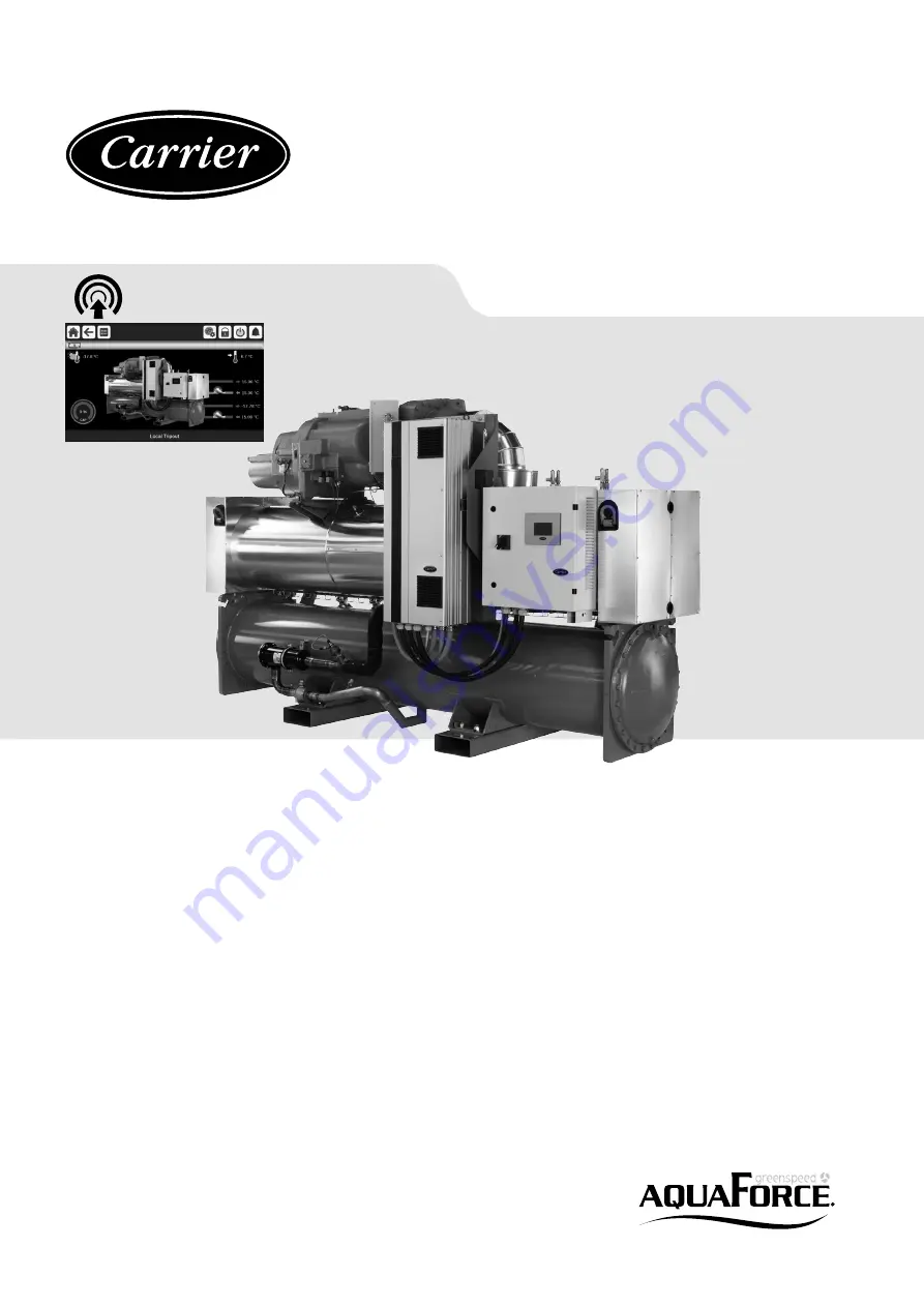
SmartVu™
Variable-Speed Water-Cooled Liquid Chillers/
Variable-Speed Water-to-Water Heat Pumps
30XW-V/30XWHV
Nominal cooling capacity: 587-1741 kW
Nominal heating capacity: 648-1932 kW
50 Hz


