


The gas service pressure must not exceed 0.5 psig (14-in. wc), and
no less than 0.16 psig (4.5-in. wc).
Thermostat wire connections at R and W/W1 are the minimum
required for gas heating operation. W2 must be connected for
2-stage heating thermostats. C
OM
, Y/Y2, and G are required for
cooling, heat pumps, and some clock thermostats. These must be
made at the 24-v terminal block on the control. (See Fig. 11.)
This furnace can be installed with either a single-stage heating or
a 2-stage heating thermostat.
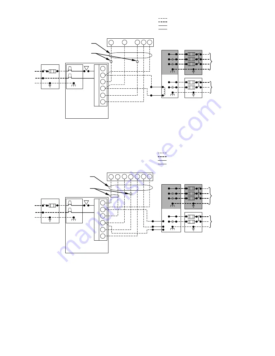
For single-stage thermostats, connect thermostat W to W/W1 at
furnace control terminal block. (See Fig. 9.) For single-stage
thermostats, the control will determine, based on length of previ-
ous heating on and off cycles, when to operate in low- and
high-gas heat for optimum comfort. Setup switch-2 (SW-2) must
be in the factory-shipped OFF position. See Fig. 12 and Tables 6
and 7 for setup switch information.
If a 2-stage heating thermostat is to be used, move SW-2 to ON
position at end of furnace installation. This overrides built-in
control process for selecting high and low fire and allows the
2-stage thermostat to select gas heating modes. The W2 from
thermostat must be connected to W2 on control terminal block.
(See Fig. 10.)
Fig. 9—Heating and Cooling Application Wiring Diagram 1-Stage Thermostat and Condensing Unit
A99071
115-V FUSED
DISCONNECT
SWITCH
(WHEN REQUIRED)
JUNCTION
BOX
CONTROL
BOX
24-V
TERMINAL
BLOCK
TWO-WIRE
HEATING-
ONLY
FIVE
WIRE
1-STAGE THERMOSTAT TERMINALS
FIELD-SUPPLIED
FUSED DISCONNECT
CONDENSING
UNIT
FURNACE
COM
R
W
Y
R
G
C
GND
GND
GND
GND
GND
GND
FIELD 24-V WIRING
FIELD 115-, 208/230-, 460-V WIRING
FACTORY 24-V WIRING
FACTORY 115-V WIRING
208/230- OR
460-V
THREE
PHASE
208/230-V
SINGLE
PHASE
WHT
BLK
WHT
BLK
W/W1
W2
Y/Y2
G
NOTES:
1. Connect Y-terminal as shown for proper operation.
2. Some thermostats require a "C" terminal connection as shown.
3. If any of the original wire, as supplied, must be replaced,
use same type or equivalent wire.
Fig. 10—Heating and Cooling Application Wiring Diagram 2-Stage Thermostat and Condensing Unit
A99072
115-V FUSED
DISCONNECT
SWITCH
(WHEN REQUIRED)
JUNCTION
BOX
CONTROL
BOX
24-V
TERMINAL
BLOCK
THREE-WIRE
HEATING-
ONLY
SEVEN
WIRE
2-STAGE THERMOSTAT TERMINALS
FIELD-SUPPLIED
FUSED DISCONNECT
2-SPEED
CONDENSING
UNIT
FURNACE
G
R
W2
Y2
G
Y1
C
GND
GND
GND
GND
GND
GND
FIELD 24-V WIRING
FIELD 115-, 208/230-, 460-V WIRING
FACTORY 24-V WIRING
FACTORY 115-V WIRING
208/230- OR
460-V
THREE
PHASE
208/230-V
SINGLE
PHASE
Y2
Y1
C
WHT
BLK
WHT
BLK
W1
R
W2
COM
W/W1
Y/Y2
NOTES:
1. Connect Y-terminal as shown for proper operation.
2. Some thermostats require a "C" terminal connection as shown.
3. If any of the original wire, as supplied, must be replaced,
use same type or equivalent wire.
10
→
→
Summary of Contents for 58TUA
Page 23: ...23 ...