


2. Weatherstripping has been added on operable windows and
doors, and/or
3. Caulking or sealants are applied to areas such as joints around
window and door frames; between sole plates and floors;
between wall-ceiling joints; between wall panels; at penetra-
tions for plumbing, electrical, and fuel lines; and at other
openings.
If combustion and ventilation air must be supplied to an uncon-
fined space from outside, an opening with a FREE AREA of not
less than 1 sq in. per 1000 Btuh of total input of all appliances
within unconfined space (but not less than 100 sq in.) must be
provided. This opening must be located such that it can not be
blocked at any time.
When furnace is installed in a closet or enclosure, 2 ventilation
openings, with OPEN AREA as dimensioned in example below
are required for combustion air. The openings should be located
about 6 in. from top and bottom of enclosure at front of furnace.
For a confined space, where air is taken from an interior space, 2
permanent openings of equal area are required. One opening must
be within 12 in. of ceiling and the other within 12 in. of floor. Each
opening must have a free area of at least 1 sq in. per 1000 Btuh of
total input rating but not less than 100 sq in.
If outside air is supplied to a confined space, then the 2 openings
must be equal and located as above. The free area of each must be:
1. One sq in. per 4000 Btuh of total input rating when air is
directly communicated from outdoors.
2. One sq in. per 4000 Btuh of total input rating when air is
brought in through vertical ducts.
3. One sq in. per 2000 Btuh of total input rating when air is
transferred through horizontal ducts.
When ducts are used to supply air, they must be of the same cross
sectional area as free area of openings to which they connect.
The minimum dimension of rectangular air ducts must not be less
than 3 in.
In calculating free area, consideration shall be given to blocking
effect of louvers, grilles, or screens protecting openings. Screens
used shall not be smaller than 1/4-in. mesh and shall be readily
accessible for cleaning. If free area through a design of louver or
grille is known, it shall be used in calculating size design and free
area specified. If design and free area are not known, it may be
assumed that wood louvers have 20 percent free area and metal
louvers and grilles have 60 percent free area. Louvers shall be
fixed in open position or interlocked with furnace so they open
automatically at furnace start-up and remain open during furnace
operation.
Do not block combustion-air openings in the furnace. Any
blockage will result in improper combustion which may result
in a fire hazard and/or cause bodily harm.
The lack of a proper amount of combustion air can lead to serious
furnace operational problems. Some of these problems are:
1. Excessive oil burner after drip and oil fumes.
2. Sooting.
3. Melted oil burner couplings and/or ignitor/relay control.
4. A condition where air band or air shutter settings must be
more open than normal to achieve proper combustion.
5. Lockouts on start-up.
Step 2—Duct Work Recommendations
The proper sizing of warm air ducts is necessary to ensure
satisfactory furnace operation. Duct work should be in accordance
with the latest editions of NFPA-90A (Installation of Air Condi-
tioning and Ventilating Systems) and NFPA-90B (Warm Air
Heating and Air Conditioning Systems) or Canadian equivalent.
The supply duct work should be attached to flanged opening
provided at discharge end of furnace. See Fig. 5 for dimensions of
this opening.
The following recommendations should be followed when install-
ing duct work:
1. Install locking-type dampers in all branches of individual
ducts to balance out system. Dampers should be adjusted to
impose proper static at outlet of furnace.
2. A flexible duct connector of noncombustible material should
be installed at unit on both supply- and return-air systems. In
applications where extremely quiet operation is necessary, the
first 10 ft (if possible) of supply and return ducts should be
internally lined with acoustical material.
3. In cases where return-air grille is located close to fan inlet,
there should be at least one 90° air turn between fan inlet and
grille. Further reduction in sound level can be accomplished
by installing acoustical air turning vanes or lining duct as
described in item 2 above.
4. When a single air grille is used, duct between grille and
furnace must be the same size as return opening in furnace.
Return-air grilles and warm air registers MUST not be
obstructed.
When supply ducts carry air circulated by furnace to areas
outside spaces containing furnace, return air MUST also be
handled by a duct sealed to furnace casing and terminating
outside space containing furnace. Incorrect duct work termi-
nation and sealing will create a hazardous condition which
could lead to bodily harm.
When installing furnace with cooling equipment for year-round
operation, the following recommendations must be followed for
series or parallel airflow:
1. In series airflow applications, coil is mounted after furnace in
an enclosure in supply-air stream. The furnace blower is used
for both heating and cooling airflow.
The coil MUST be installed on air discharge side of furnace.
Under no circumstances should airflow be such that cooled,
conditioned air can pass over furnace heat exchanger. This
will cause condensation in heat exchanger and possible
failure of heat exchanger which could lead to a fire hazard
and/or a hazardous condition which may lead to bodily harm.
Heat exchanger failure due to improper installation may not
be covered by warranty.
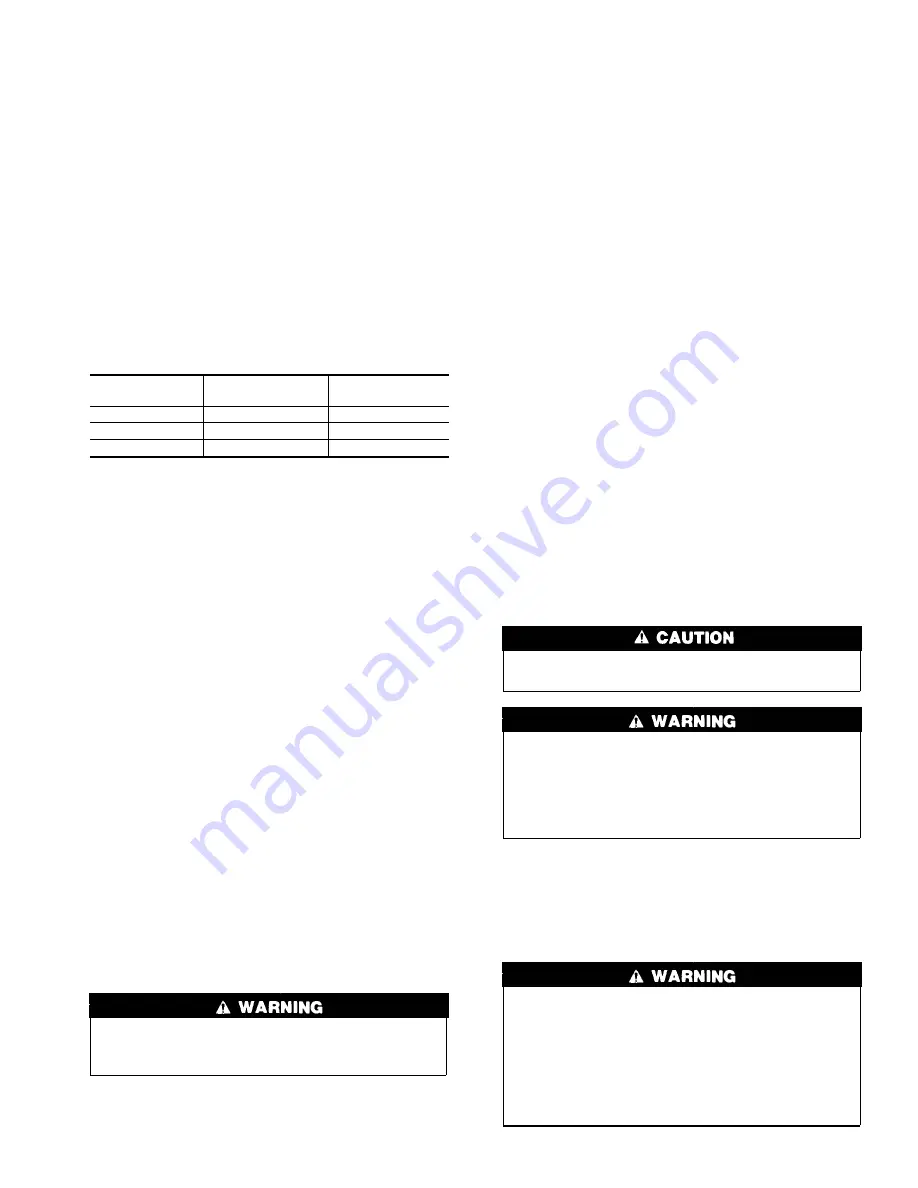
For Example:
UNIT
SIZE
LENGTH
(IN.)
HEIGHT
(IN.)
105-12
18
9
125-16
20
10
155-20
20
10
3
→
→


