background image

12

Palletised

Size 1

10

1600

1100

1500

320

Size 2

10

1700

1350

1500

450

Size 3

10

1 700

1 350

1 500

430

Size 4

6

1 800

1 350

1 200

410

Units per

pallet

Length

(mm)

Width

(mm)

Height

(mm)

Weight

(kg)

NOTE:
When receiving a shipment of units, check at once that none
of the packages has been damaged. To maintain the protec-
tion of the packaging as long as possible, do not open any
package until just before a unit is to be installed.

2.3 - ULTRA packaging

Packaged on wooden pallets and protected by heat-shrunk or
stretchable plastic film.

NOTE:
If “Export” packaging is needed, please contact your local
Carrier representative.

2.4 - Receiving a shipment - installation methods

When receiving a shipment, check the condition of the goods
and report any damage in transit to the shipping company. Do
not unpack the units until just before they are due to be instal-
led, and make sure they are as close as possible to the installa-
tion site when unpacking them. Do not stack the units and do
not place heavy articles of any sort on them.

WARNING:
When moving the units do not use water pipe connections or
condensate drain stubs, valves or flexible pipes as handles.

The presence of electrical components creates hazards to those
installing and servicing these units. Only properly qualified
electricians may be authorised to install, service and repair
these units. Some routine maintenance such as cleaning of the
coils and filter replacement may be entrusted to non-skilled
personnel. Before carrying out any work, qualified technicians
must familiarise themselves with the contents of this manual
and all informative tags and labels attached to the units. It is
essential to adhere to all applicable safety regulations. Wear
eye protectors, work gloves and non-flammable clothing when
soldering or brazing. Always have a fire extinguisher of the
appropriate type close at hand.

WARNING:
Disconnect the power supply to the unit and to any accesso-
ries before carrying out any work on a unit.

Do not install a unit where flammable gases or products of an
acidic or alkaline character may be present. The copper/alumi-
nium coil or plastic components inside the unit could suffer
irreparable corrosion damage in their presence.

WARNING:
Failure to take proper account of the above advice and
unauthorised modification of the electrical connections will
render the warranty on the product null and void.

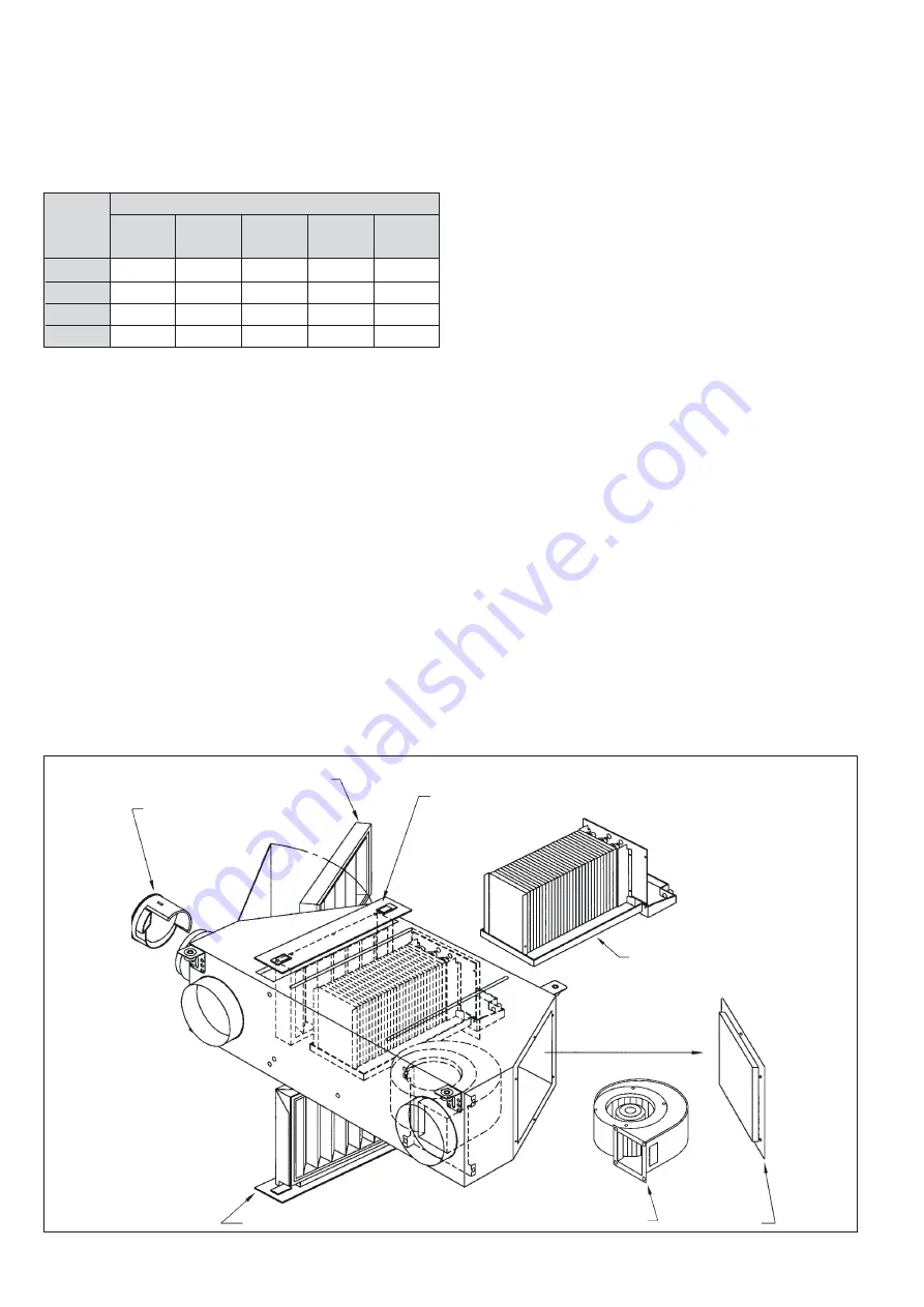
FRESH AIR CONTROLLER

LATERAL FILTER ACCESS OPTION

FILTER TOP ACCESS
OPTION

FILTER ACCESS OPTION FROM BELOW

DRAIN PAN AND 
COIL ASSEMBLY

FAN MOTOR ASSEMBLY

FAN ACCESS 

PANELS

Summary of Contents for 42BJ 1.6 ULTRA

Page 1: ...42BJ ULTRA Sizes 1 6 2 6 4 7 Local Air Conditioning Unit Installation manual Hot chilled water inlet outlet Thermophonic ducting Supply return ModuBoot Fresh air inlet ULTRA ...

Page 2: ...The photo shown on the front cover is solely for information and not contractually binding ...

Page 3: ... 7 2 Removing the water coil 18 7 3 Coil inlet outlet positions 19 8 WATER FLOW CONTROL VALVES 21 8 1 Description 21 8 2 Replacing actuators 21 8 3 Electrical circuit diagrams for actuators 21 8 4 Replacing a valve body 21 9 FLEXIBLE WATER HOSES 22 10 AIR FILTER AND ACCESS 23 10 1 Description 23 10 2 Replacing the air filter 23 11 ELECTRIC HEATER 24 11 1 Electric resistance heater size 1 6 24 11 2...

Page 4: ...in three sizes with a choice of three motor drives and is capable of air conditioning rooms ranging from 25 m2 to 50 m2 in area Its main components are a motorised variable speed centrifu gal fan a high efficiency air filter a fresh air supply fitted with an air flow control unit a chilled water cooling coil and either a hot water heating coil or an electric heating unit Flexible thermally insulat...

Page 5: ...uspended ceilings or below false floors Their casings are built of 10 10 galvanised sheet steel lined with 13 mm of fibre wool which in turn is protected by a layer of erosion resistant neoprene The drive motor access door is coated with 13 mm of fibre wool and the air filter access panel is covered with 5 mm of foam NOTE Operating limits air discharge temperature 12 C when the unit is installed i...

Page 6: ...gle wheel double inlet double inlet double inlet Air flow at high speed l s m3 h 166 600 194 700 264 950 Static pressure at high speed Pa 80 80 85 Motor Supply 230 V single phase 50 Hz U 10 10 10 Asynchronous inherent overload protection Nbr of 2 2 2 Permanent capacitor class B insulation poles varnish class F protection IP 44 Maximum power at high speed W 219 245 183 Nominal current at high speed...

Page 7: ... Size 1 6 Removable drain pan and coil assembly Fan motor access door Filter access side door Clearance for lower filter access panel Removable drain pan and coil assembly Electric heater Fan motor access door Filter access side door Clearance for lower filter access panel ...

Page 8: ...2 1 Clearances for maintenance mm continued Size 4 7 220 200 1100 300 600 750 120 Clearance for lower filter access panel Fan motor access door Removable drain pan and coil assembly Filter access side door ...

Page 9: ...9 Sizes 2 6 and 4 7 Grommet Grommet 2 2 Dimensional drawings continued 2 2 2 Template for fixing threaded rods mm Size 1 6 ...

Page 10: ...control valves 10 Filter access door 11 Fan motor access door 12 Three speed fan motor assembly 13 Condensate drain pan 14 Electric heater Ø 16 condensate outlet Detail rep 1 Grommet Legend 1 Suspension lugs 2 Coil hot chilled water 3 Electromechanical controller 4 Air filter 5 Hot chilled water supply and return connections 6 Fresh air connection 7 Return air duct connection 8 Supply air duct con...

Page 11: ...rommet Legend 1 Suspension lugs 2 Coil hot chilled water 3 Electromechanical controller 4 Air filter 5 Hot chilled water supply and return connections 6 Fresh air connection 7 Return air duct connection 8 Supply air duct connection 9 Water flow control valves 10 Filter access door 11 Fan motor access door 12 Three speed fan motor assembly 13 Condensate drain pan 14 Electric heater ...

Page 12: ...onents creates hazards to those installing and servicing these units Only properly qualified electricians may be authorised to install service and repair these units Some routine maintenance such as cleaning of the coils and filter replacement may be entrusted to non skilled personnel Before carrying out any work qualified technicians must familiarise themselves with the contents of this manual an...

Page 13: ...med by electromagnetic interfe rence unless they are installed and used in accordance with these instructions The components making up these controls systems conform to the requirements of electromagnetic com patibility in residential and industrial areas They also com ply with the low voltage directive 3 3 General installation recommendations IMPORTANT In general units fitted with controls loops ...

Page 14: ...f fixing the threaded hangers not supplied by Carrier will depend upon the nature and condition of the cei ling If in doubt seek professional advice The maximum dia meter of the hangers is 8 mm WARNING When moving a unit do not use the water pipe connections condensate drain pan valves flexible pipes or electrical cables as handles Lift the unit and align it on the threaded hangers Screw the nuts ...

Page 15: ...nd before start up remove the protective film from the diffuser NOTE ULTRAs are connected to the diffusers by ducts The pressu re drop in the ducts must be compatible with the capacity of the unit The inner surfaces of the duct must be as smooth as possible Avoid sharp bends Check that there are no leaks or kinks and that there is no dirt or installation debris inside the ducts Debris within the d...

Page 16: ...estricters Replace the fresh air controller in the spigot Reconnect the fresh air duct to the spigot NOTE Two types of plastic spigot may be fitted to the ULTRA depending on the capacity of the fresh air controller chosen One spigot can accept only the 8 3 l s or 30 m3 h controller The other one can accept only the field modifiable 16 6 l s or 60 m3 h controller This means there is no possibility ...

Page 17: ...he fan assembly is held in place by one hexagon head screw 8 mm AF and three lugs Remove this screw and slide the assembly free of the lugs d Replace the fan motor assembly and follow the procedu re in reverse order to complete the installation 6 3 Replacing the capacitor a Disconnect the power supply to the ULTRA before car rying out any work on the unit b Unscrew the 6 hexagon head screws 8 mm A...

Page 18: ...changers purges drains isolating valves etc according to the analysis results The results must be in accordance with the values shown below Total hardness in French degrees 10 TH 15 Chloride CL 10 mg l Sulphate SO4 2 30 mg l Nitrate NO3 0 mg l Dissolved iron 0 5 mg l Dissolved oxygen 4 O2 9 mg l Carbon dioxide CO2 30 mg l Resistivity 2000 Resistivity 5000 Ωcm pH 6 9 pH 8 7 2 Removing the water coi...

Page 19: ...1 EXT DIAMETER 18 MM DETAIL OF COIL CONNECTOR DETAIL OF VALVE CONNECTOR DETAIL OF VALVE CONNECTOR DETAIL OF COUPLING CONNECTOR HOT WATER IN CHILLED WATER IN CHILLED WATER OUT HOT WATER OUT HOT WATER IN CHILLED WATER IN CHILLED WATER OUT 7 3 Coil inlet outlet positions dimensions in mm 7 3 1 ULTRA sizes 1 6 and 2 6 Two port valves ...

Page 20: ...M HT 1 2 GAS CONNECTION WITH TURNED UP FLANGE 15 21 EXT DIAMETER 18 MM DETAIL OF COIL CONNECTOR DETAIL OF VALVE CONNECTOR DETAIL OF VALVE CONNECTOR DETAIL OF COUPLING CONNECTOR HOT WATER IN CHILLED WATER IN CHILLED WATER OUT HOT WATER OUT HOT WATER IN CHILLED WATER IN CHILLED WATER OUT 7 3 Coil inlet outlet positions continued dimensions in mm 7 3 2 ULTRA size 4 7 Two port valves ...

Page 21: ...ire from the appropriate terminal c Uncouple the faulty actuator Reverse the removal proce dure described above when installing the replacement motor WARNING Ensure that the actuator is firmly screwed to the valve body maximum torque 15 N m 8 3 Electrical circuit diagrams for actuators 8 4 Replacing a valve body a Disconnect the power supply to the unit before carrying out any work on a unit b Clo...

Page 22: ...nding radius 35 mm non insulated 75 mm insulated The flexible water pipes are designed to carry treated or untreated water maximum 40 concentration of ethylene glycol or propylene glycol Maximum hot water temperature 90 C Operating pressure 16 bars Test pressure 24 bars Connections 1 2 BSP threaded nut CONNECTOR NUT THREAD DEPTH 9 5 MM INTERNAL THREAD 1 2 TO STANDARD NFE 03 005 PROVIDE LEAKTIGHT S...

Page 23: ...ted at the suction end of the fan and could therefore overflow if the air filter became clogged This is because the partial vacuum inside the unit could stop the condensate from draining normally 10 2 1 Access from the side To access the filter open the latch open the hinged access door and remove the filter from its housing by releasing the two clips which hold it in place When replacing the filt...

Page 24: ...ich is fitted with a packing gland to admit the power supply cable The heater unit is fitted with a manually reset safety thermo stat This normally closed contact is triggered by a rise in tem perature to 112 C 0 16 The safety thermostat protects the unit from overheating gene rally the result of electricity passing through the heater when there is insufficient air flow The thermostat can be reset...

Page 25: ... 4 2 Wiring diagram for one stage of an electric heater for a size 2 6 ULTRA 11 4 3 Wiring diagram for one stage of an electric heater for a size 4 7 ULTRA CAUTION It is vital to disconnect the ULTRA from the main power sup ply before carrying out any work on the electric heater SIZE 1 ELECTRIC HEATER POSITION ELECTRIC HEATER REMOVE COPPER CONNECTION STRIPS BRIDGE Green Yellow Brown Blue CABLE FRE...

Page 26: ...f the quick connect terminal block see section describing room thermostats 12 2 The various ULTRA configurations available Each ULTRA can be fitted with one or two on off valves two or three ports and flexible water pipes depending how the hea ter is configured a The ULTRA is fitted with a 5 row cooling coil 2 pipes Operates in cooling mode only This option includes a 2 port on off valve and two i...

Page 27: ...he water flow control valve the changeover between heating and cooling modes takes place automatically in accordance with the following diagram BLUE BROWN BROWN RED BLACK ACTUATOR FOR COOLING VALVE CHANGEOVER Differential 11 1 K 3 3 CM Cooling mode HM Heating mode θ Water temperature in C FM ...

Page 28: ...terie électrique Vitesse 2 Vitesse 3 GV L alimentation thermostat 230V a c N alimentation thermostat 230V a c Vitesse 1 PV Ouverture vanne froide Alimentation 230V 50Hz 1 ph 3G2 5mm2 Protection T 16A N L 2 tubes 2 fils 12 5 Master slave control two pipe electric heater configuration Cooling valve Heating valve Fan Supply 230 V 50 Hz 1 phase 3G1 5 mm2 Protection T2A Supply 230 V 50 Hz 1 phase 3G2 5...

Page 29: ...TRA is supplied without a ter minal strip power relay or plastic protective cover This option is specially provided for installers who wish to fit the control system to the ULTRA themselves 12 5 1 Wiring diagrams with cable bundles ready to connect Fan wiring Electric heater wiring HIGH SPEED SECTION 5 x 1 mm2 BLUE RED GREY BLACK GREEN YELLOW FAN MEDIUM SPEED LOW SPEED NEUTRAL BROWN BLUE GREEN YEL...

Page 30: ... Commande vanne froide Vitesse 1 PV N LIAISON 7 x 0 75mm2 12 5 4 Five row coil cooling 12 5 3 Five row coil with heating cooling changeover switch Power supply 230 V 50 Hz 1 phase 3 x 1 5 mm2 Protection T2A Cables 6 x 0 75 mm2 Cooling valve Power supply 230 V 50 Hz 1 phase 3 x 1 5 mm2 Protection T2A Fan Cables 7 x 0 75 mm2 Fan Speed 1 LS Speed 2 Speed 3 HS L Thermostat supply 230 V a c N Thermosta...

Page 31: ...ture vanne froide N alimentation thermostat 230V a c Vitesse 1 PV Vitesse 2 Configuration 2 tubes et batterie électrique Commande chauffage électrique LIAISON 7 x 0 75mm2 Power supply 230 V 50 Hz 1 phase 3G 2 5 mm2 Protection T16A Power supply 230 V 50 Hz 1 phase 3G 1 5 mm2 Protection T2A Cables 6 x 0 75 mm2 Cooling valve Fan Speed 1 LS Speed 2 Speed 3 HS L Thermostat supply 230 V a c N Thermostat...

Page 32: ...g 2 maximum angle 15 on page 34 3 Install the detector block Use the rubber tube supplied to connect the detector to the condensate drain Fig 2 B Connect the 6 mm bore flexible tube to the outlet stub on the detector Connect the small 6 mm bore flexible tube to the vent outlet of the detector block Attach the detector block support to the aluminium bracket with the double sided adhesive tape suppl...

Page 33: ...e the alarm threshold The alarm condition no longer applies when the level is below the alarm threshold The device includes a potential free changeover switch with a capacitance of 8 A 250 V resistive load The alarm contact on the drain pump is a Normally Open or Normally Closed type and therefore If the condensate level is below the alarm threshold no alarm condition the contact is open if the wi...

Page 34: ...CK SUPPORT BRACKET DETECTOR BLOCK SUPPORT LABEL SHOWING THE ATTACHMENT PLAN FOR FIXING THE PUMP BLOCK SUPPORT BRACKET ALUMINIUM DETECTOR BLOCK BRACKET FLEXIBLE TUBES 2 A 2 B Pump kit Fig 1 PUMP BLOCK SUPPORT BRACKET FIXING SCREWS Installing the detector on the drain pan Fig 2 ...

Page 35: ...E NORMALLY CLOSED PUMP OUTLET ELECTRICAL CONNECTION NORMALLY OPEN COMMON LABEL SHOWING THE ATTACHMENT PLAN Pump connections Fig 3 Pump block installation Fig 4 RJ11 CONNECTION THELEPHONE TYPE PUMP INLET CONDANSATE DRAIN FLEXIBLE TUBE Ø 6 SMALL FLEXIBLE TUBE DON T PINCH THE TUBE ...

Page 36: ... climate in your region simulation of the heating and cooling loads according to your needs measuring storing and display of the air temperatures and the air distribution pattern taking into account your cli matic and architectural constraints even at climatic extremes optimisation of the physical location of the air terminals in your building walls or ceilings determination and control of the sou...

Reviews: