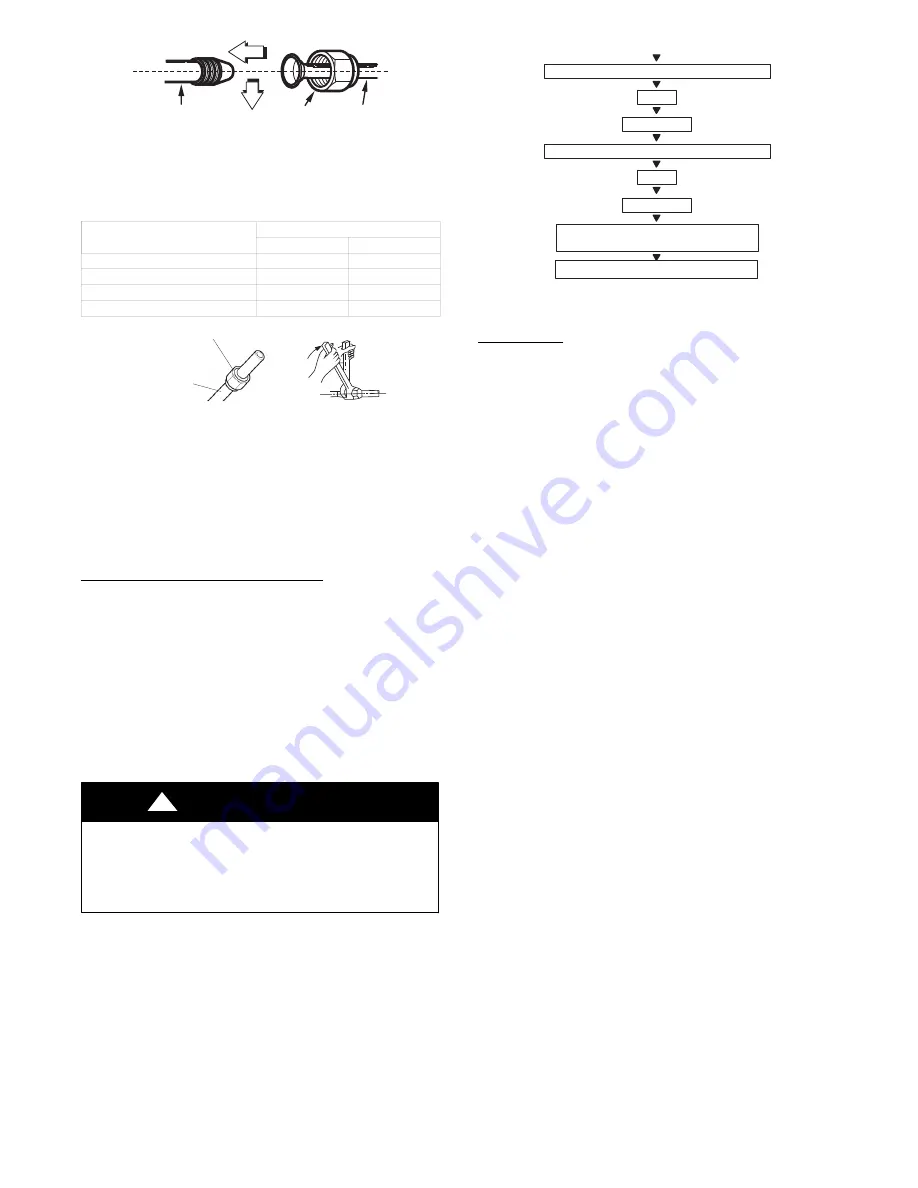
background image

16

Indoor unit tubing

Flare nut

Piping

Fig. 40

 - 

Align Pipe Center

h. Connect both the liquid and gas piping to the indoor unit.

i. Tighten the flare nut using a torque wrench as specified in

Table 7.

Table 7—Tightening Torque

PIPE DIAMETER INCH (mm)

TIGHTENING TORQUE

Ft-lb

N-m

Ø

1/4

” 

(6.35)

10 to 13

13.6 to 17.6

Ø

3/8

” 

(9.52)

24 to 31

32.5 to 42.0

Ø

1/2

” 

(12.7)

37 to 46

50.1 to 62.3

Ø

5/8

” 

(15.88)

50 to 60

67.7 to 81.3

Flare nut

Copper tube

Fig. 41

 - 

Tighten the Flare Nut

6. Connect the drain line. The drain line must not have a trap

anywhere in its length. The drain line must pitch downwards.
The drain line must be insulated up to the outside wall.

NOTE:  For applications where gravity cannot be used for
drainage, a condensate pump accessory is available. Consult the
condensate pump Installation Instructions for more information.

WIRELESS REMOTE CONTROL INSTALLATION

Mounting Bracket (if installed on the wall)

1. Use the two screws supplied with the control to attach the

mounting bracket to the wall in a location selected by the
customer and within operating range.

2. Install the remote control batteries.

3. Place the remote control into the remote control mounting

bracket.

4. For remote control operation, refer to unit owner’s manual.

WIRED REMOTE CONTROLLER

For setup instructions, refer to the wired controller installation
manual. Refer to Fig. 23 for the 4 and 5 Pin connections for the
different wired remote controllers.

UNIT DAMAGE HAZARD

Failure to follow this caution may result in equipment
damage or improper operation.

Never use the system compressor as a vacuum pump.

CAUTION

!

Refrigerant tubes and the indoor coil should be evacuated using the
recommended deep vacuum method (500 microns). The alternate
triple evacuation method may be used if the procedure outlined
below is followed. Always break a vacuum with dry nitrogen.

FINAL TUBING CHECK

IMPORTANT: Ensure certain factory tubing on the indoor unit
has not shifted during shipment. Ensure tubes are not rubbing
against each other or any sheet metal. Pay close attention to the
feeder tubes, making sure the wire ties on the feeder tubes are
secure and tight.

EVACUATE

EVACUATE

CHECK FOR TIGHT, DRY SYSTEM

(IF IT HOLDS DEEP VACUUM)

BREAK VACUUM WITH DRY NITROGEN

WAIT

RELEASE CHARGE INTO SYSTEM

EVACUATE

BREAK VACUUM WITH DRY NITROGEN

WAIT

Fig. 42

 - 

Triple Evacuation Method

START−UP

Test Operation

Perform a test operation after completing a gas leak and electrical
safety check.

1. Press ON/OFF (on the remote control) to begin testing.

NOTE:  A protection feature prevents the air conditioner from
being activated for approximately 3 to 4 minutes.

2. Press MODE and select the COOLINGHEATINGFAN

modes to ensure all the functions work correctly.

3. To run the test using the manual button in the indoor unit:

(1.) Open the indoor unit’s front panel;

(2.) Press manual switch once to energize the unit. Set

conditions of the manual operation are as follows:
· Preset set point: 76

_

F (24

_

C)

· Fan speed: AUTO
· Discharge air direction: Pre−set position based on
   operation in COOL or HEAT mode.

4. Be sure to set the manual switch to OFF (by pressing it

twice again) after finishing the test operation.

SYSTEM CHECKS

1. Conceal the tubing where possible.

2. Ensure the drain tube slopes downward along its entire

length.

3. Ensure all tubing and connections are properly insulated.

4. Fasten the tubes to the outside wall, when possible.

5. Seal the hole through which the cables and tubing pass.

INDOOR UNIT

1. Do all the remote control buttons function properly?

2. Do the display panel lights work properly?

3. Does the air deflection louver function properly?

4. Does the drain work?

OUTDOOR UNIT

1. Are there unusual noises or vibrations during operation?

Explain Following Items To Customer
(with the aid of the Owner’s Manual):

1. How to turn the air conditioner on and off; selecting

COOLINGHEATING and other operating modes;
setting a desired temperature; setting the timer to
automatically start and stop the air conditioner operation;
and all other features of the remote control and display
panel.

2. How to remove and clean the air filter.

3. How to set air deflection louver.

4. Explain care and maintenance.

5. Present the owner’s manual and installation instructions to

customer.

Summary of Contents for 40MBCQ

Page 1: ... actual model may differ slightly NOTE Read the entire instruction manual before starting the installation TABLE OF CONTENTS PAGE SAFETY CONSIDERATIONS 2 PARTS LIST 3 SYSTEM REQUIREMENTS 4 WIRING 4 DIMENSIONS 5 CLEARANCES 7 INSTALLATION TIPS 8 INDOOR UNIT INSTALLATION 8 ELECTRICAL DATA 14 CONNECTION DIAGRAMS 15 START UP 16 TROUBLESHOOTING 17 ...

Page 2: ...s hazards which will result in severe personal injury or death WARNING signifies hazards which could result in personal injury or death CAUTION is used to identify unsafe practices which may result in minor personal injury or product and property damage NOTE is used to highlight suggestions which will result in enhanced installation reliability or operation WARNING ELECTRICAL SHOCK HAZARD Failure ...

Page 3: ...r unit is higher than the indoor unit prevent rain from flowing into the indoor unit along the connection pipe by creating a downward arc in the connection pipe before it enters the wall to the indoor unit This ensures that rain drips from the connection pipe before entering the wall Piping and the interconnecting wiring are field supplied Fig 1 is only a sketch Different models may differ slightl...

Page 4: ...d EMF area and communication issues exist a 14 2 stranded shielded wire can be used to replace L2 and S between outdoor unit and indoor unit landing the shield onto ground in the outdoor unit only Recommended Connection Method for Power and Communication Wiring 36K through 48K Power Wiring The main power is supplied to the outdoor unit The field supplied power wiring from the outdoor unit to the i...

Page 5: ...m 25 79 655 28 15 715 25 79 655 28 15 715 25 79 655 28 15 715 35 43 900 40 75 1035 35 43 900 40 75 1035 35 43 900 40 75 1035 Depth In mm 25 79 655 28 15 715 25 79 655 28 15 715 25 79 655 28 15 715 35 43 900 40 75 1035 35 43 900 40 75 1035 35 43 900 40 75 1035 Weight Gross Lbs kg 41 88 19 9 92 4 5 41 88 19 9 92 4 5 46 3 21 9 92 4 5 54 23 24 6 17 64 8 66 14 30 17 64 8 72 53 32 9 17 64 8 Weight Net 3...

Page 6: ...ole for 75 Fresh air intake 2 16 55 3 15 80 4 install hanger Gas side Liquid side E parts box 5 31 135 3 54 90 Panel Body D D 3 62 92 D D D D D D A B C D Capacity Btu h 24K mm 160 75 205 50 inch 6 30 2 95 8 07 1 97 36K mm 160 95 245 60 inch 6 30 3 74 9 65 2 36 48K mm 160 95 287 60 inch 6 30 3 74 11 30 2 36 3 15 80 26 77 680 30 71 780 33 07 840 3 62 92 3 62 92 37 40 950 3 62 92 Fig 3 Indoor Unit Si...

Page 7: ...7 CLEARANCES Fig 4 Cassette Unit Clearance ...

Page 8: ...nsure the install site can withstand a weight four times of the unit s If not reinforce the site prior to installation Refer to the install cardboard to determine where the location should be reinforced IMPORTANT To guarantee a good performance the unit must be installed by professional personnel in accordance with this manual IMPORTANT Drilling holes in the ceiling must be performed by profession...

Page 9: ...eeding further For an installation example see Fig 10 1 2 3 4 Fig 10 Installation Clearances 1 Ceiling slab 2 Expansible hook optional 3 Installation hook optional 4 False ceiling NOTE For a non standard installation contact your dealer for details When installing optional accessories review the optional accessories list in the installation manual Depending on field conditions it may be easier to ...

Page 10: ...densation 1 Indoor drain pipe 2 Drain socket Unit mm 1 2 5 7 0 5 1 1 5m 300 11 8in 6 5 4 3 n i 7 8 0 2 2 n i 5 9 2 0 5 7 n i 3 0 n i 9 0 2 0 3 5 3 5ft Fig 16 Drain Setup Pipe 1 Ceiling slab 2 Hanger bracket 3 Adjustable range 4 Drain raising pipe 5 Drain hose 6 Metal clamp Connect the drain hose to the drain raising pipes and insulate them Connect the drain hose to the drain outlet on the indoor u...

Page 11: ...m 2 Water receiver ElectricalWiring 1 Remove the indoor unit control box lid 2 Follow the Wiring Diagram label attached to the indoor unit s control box lid to wire the outdoor unit indoor unit and the wired remote controller 3 Securely fix the wires with a field supplied clamp 4 Attach the outdoor unit cover When the electric wiring work is complete check the drainage flow during COOL running 1 C...

Page 12: ...on panel to the unit with the supplied screws see Fig 24 3 After installing the decoration panel ensure there is no space between the unit body and the decoration panel Otherwise air may leak through the gap and cause dewdrops see Fig 23 Fig 23 Eliminate Space 4 Mount the intake grille Ensure the buckles at the back of the grille are properly seated in the panel s groove 1 Decoration panel 2 Screw...

Page 13: ...N40 Connector Used for Wired Remote Control with a 4 Pin Molex plug Wired Remote Controller Available as Accessory 5 Pin Molex plug to be connected to Wired Controller s cable Grille Display 10 pin Molex plug to be connected to Control Board Grille Louver Motor Power 5 Pin Molex plug to be connected to Control Board Fig 29 Panel Cassette Connections ...

Page 14: ...ht of the indoor unit needs to be adjusted you can do so through the openings at the panel s four corners Make sure that the internal wiring and drainpipe are not affected by this adjustment ELECTRICAL DATA Table 5 Electrical Data UNIT SIZE OPER VOLTAGE INDOOR FAN MAX FUSE CB AMP OPER VOLTAGE MAX MIN V PH HZ FLA HP W MAX FUSE CB AMP 9 253 187 208 230 1 60 0 146 0 061 46 Refer to outdoor unit insta...

Page 15: ...sulation at the flare connection then fasten the piping and wiring to the wall as required Completely seal the hole in the wall 5 Piping a Cut the pipe with a pipe cutter at 90 degrees see Fig 38 b Remove the service connection if provided with the unit Oblique DŽ 90 Roughness Burr Fig 38 Pipe Cutting c Remove all the burrs from the cut cross section of the pipe avoiding any burrs inside the tubes ...

Page 16: ...t metal Pay close attention to the feeder tubes making sure the wire ties on the feeder tubes are secure and tight EVACUATE EVACUATE CHECK FOR TIGHT DRY SYSTEM IF IT HOLDS DEEP VACUUM BREAK VACUUM WITH DRY NITROGEN WAIT RELEASE CHARGE INTO SYSTEM EVACUATE BREAK VACUUM WITH DRY NITROGEN WAIT Fig 42 Triple Evacuation Method START UP Test Operation Perform a test operation after completing a gas leak...

Page 17: ...ture sensor T2 open circuit or short circuit 7 times X EC Refrigerant leakage detection 8 times X EE Water level alarm malfunction 1 time O F0 Current overload protection 2 times O F1 Open circuit or short circuit of outdoor ambient temperature sensor T4 3 times O F2 Open circuit or short circuit of condenser coil temperature sensor T3 4 times O F3 Open circuit or short circuit of Compressor disch...

Page 18: ...D 7310 W Morris St D Indianapolis IN 46231 Edition Date 10 18 Manufacturer reserves the right to change at any time specifications and designs without notice and without obligations Catalog No IM 40MBCQ 03 Replaces IM 40MBCQ 02 ...

Reviews: