


18
Install Condensate Drain
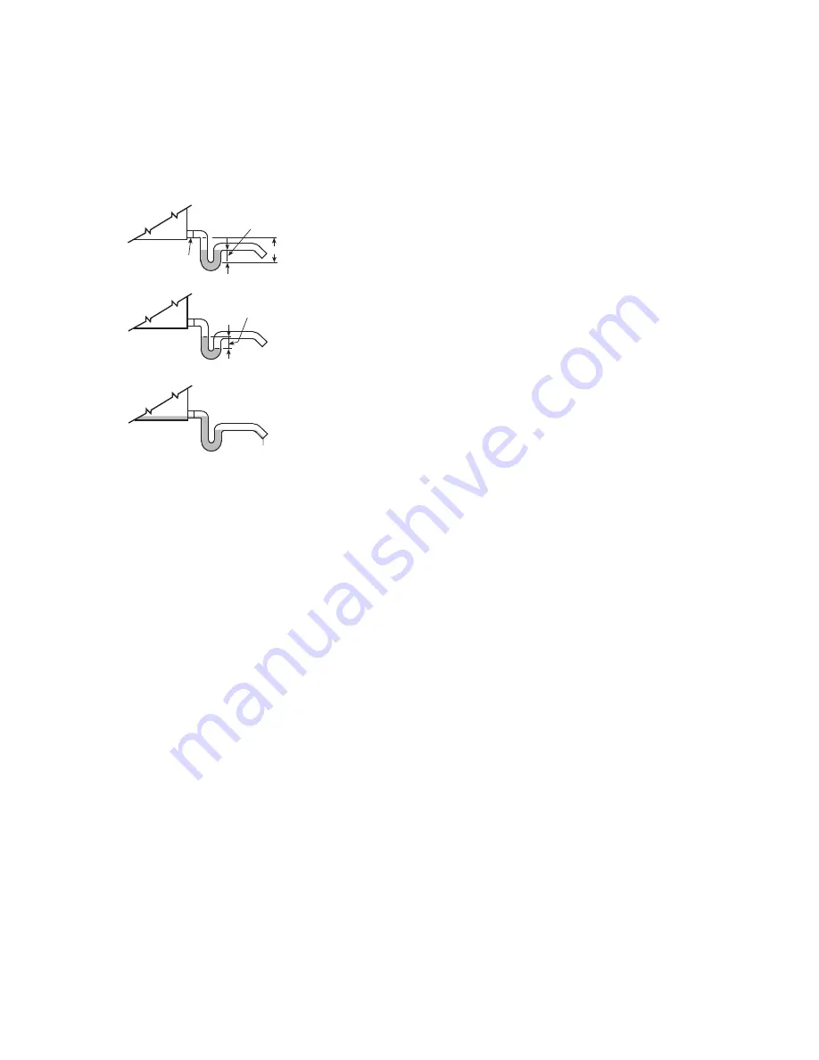
Install a trapped condensate drain line at unit drain connection.
Use 1-in. standard pipe.
Measure maximum design negative static pressure upstream from
the fan. Referring to Fig. 20, height “H” must be equal to or larger
than negative static pressure at design operating conditions. Prime
enough water in trap to prevent losing seal (Differential 1). When
the fan starts, Differential 2 is equal to the maximum negative
static pressure.
Provide freeze-up protection and insulation as required.
Fig. 20 — Condensate Drain
Variable Frequency Drive (VFD)
Variable frequency drives (VFDs) are used to modulate fan motor
speed in response to air volume requirements. To vary the motor
speed, a VFD changes the input frequency and line voltage into a
wide range of frequency and voltage outputs, while maintaining a
constant ratio of frequency to voltage. See Table for motor and
drive package data.
Since 2001, all 1-hp and greater motors supplied by Carrier for the
39L series air handling units are designed and constructed for use
with variable frequency drives. If a field-supplied motor is in-
stalled, ensure the motor is suitable for use with a VFD.
If the lead length from the VFD to the motor is greater than 25 ft,
Shaft Grounding Rings (SGR) are necessary to help dissipate in-
duced shaft voltages to ground and prevent motor bearing damage.
Install Fan Motor
For field installation of motors, be sure electrical junction box is
toward the center of the unit.
This is necessary for drive and belts
to be properly tightened. Use smallest slots in motor mounting
base that will accommodate motor and allow minimum overhang
(Fig. 28). Be sure that motor holddown bolts are tight on field-
installed motor. See Table 5 for electrical data for premium effi-
ciency EISA compliant motors.
JUNCTION BOX CONDENSATE PREVENTION
When air handlers are installed outdoors in a high humidity envi-
ronment or indoors where the apparatus room is used as a fresh air
plenum, precautions must be taken to prevent condensation from
forming inside the junction box of the internally mounted motor.
Standard installation practice is to mount the motor starter or fused
disconnect box adjacent to the air handler and enclose the power
wiring to the motor in flexible conduit.
The sheet metal housing of the disconnect switch or motor starter
is not airtight (even when a box meeting NEMA [National Electri-
cal Manufacturers Association] IV standards is used). Thus, warm
moist air can migrate through the flexible conduit to the junction
box on the motor. With the motor located inside the unit, the motor
temperature is that of the cool supply air; thus, condensate can
form inside the junction box and, possibly, on the live terminal
lugs.
To prevent the moist air from migrating through the conduit to the
motor, seal the power wires inside the flexible conduit at the motor
starter or fused disconnect.
Use a non-conductive, non-hardening sealant. Permagum (manu-
factured by Schnee Morehead) or sealing compound, thumb grade
(manufactured by Calgon), are acceptable materials.
POWER KNOCKOUTS
Panels are not provided with knockouts for the fan motor power
wiring. Openings must be drilled or punched in the exterior panels
of the unit. It is recommended that power wiring be routed through
the discharge panel whenever possible, as this panel is rarely re-
moved for service access.
FAN OFF
TRAP CONDITION WHEN FAN STARTS
FAN RUNNING AND CONDENSATE DRAINING
DIFFERENTIAL
1
DRAIN NIPPLE
DIFFERENTIAL
2
COOLING COIL
DRAIN PAN
H