


4
A00010
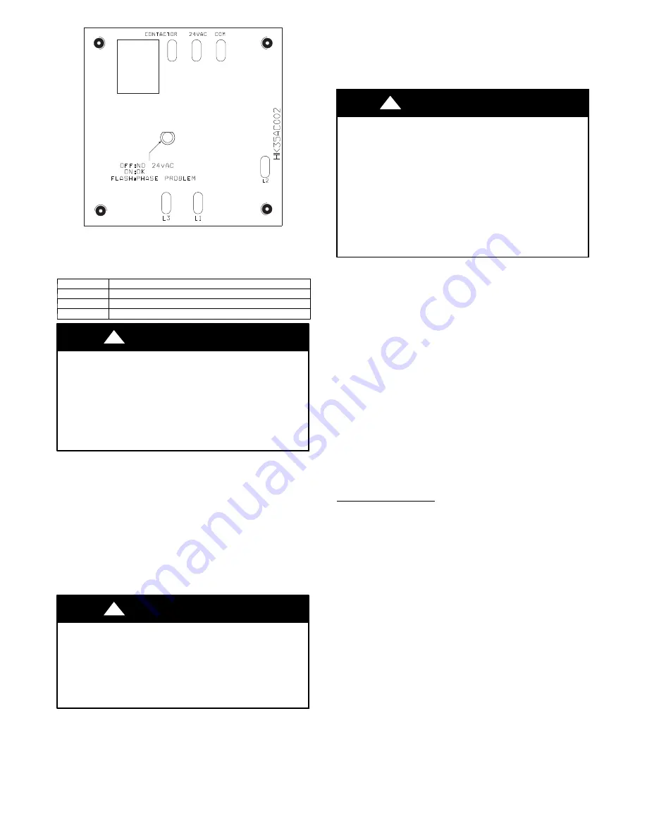
Fig. 5
---
3 Phase Monitor Control
Table 2—Phase--Monitor LED Indicators
LED
STATUS
OFF
No call for compressor operation
FLASHING
Reversed phase
ON
Normal
UNIT DAMAGE HAZARD
Failure to follow this caution may result in unit damage.
S
3--phase scroll compressors are rotation sensitive.
S
A flashing LED on phase monitor indicates reverse
rotation. (See Fig. 5 and Table 2.)
S
This will not allow contactor to be energized.
S
Disconnect power to unit and interchange 2 field wiring
leads on unit contactor.
CAUTION
!
COMPRESSOR CRANKCASE HEATER
A crankcase heater is required if refrigerant tubing is longer than
80 ft. (24.38 m).
When equipped with a crankcase heater, energize heater a
minimum of 24 hours before starting unit. To energize heater only,
set thermostat to OFF mode and close electrical disconnect to
outdoor unit.
INSTALL ELECTRICAL ACCESSORIES
Refer to individual instructions packaged with kits or accessories
when installing.
START--UP
UNIT DAMAGE AND/OR PERSONAL INJURY
HAZARD
Failure to follow this caution may result in personal injury
and/or unit component damage.
Service valve gauge ports are equipped with Schrader
valves. Wear safety glasses and gloves when handling
refrigerant.
CAUTION
!
1. Fully open liquid and vapor service valves.
2. Unit is shipped with valve stem(s) front seated (closed) and
caps installed. Replace stem caps after system is opened to
refrigerant flow. Replace caps finger--tight and tighten an
additional 1/12 turn with wrench.
3. Close electrical disconnects to energize system.
4. Set room thermostat at desired temperature. Be sure set
point is below indoor ambient temperature.
5. Set room thermostat to COOL and fan control to ON or
AUTO mode. Operate unit for 15 minutes. Check system--
refrigerant charge. (See Check Charge.)
PERSONAL INJURY and ENVIRONMENTAL
HAZARD
Failure to relieve system pressure could result in personal
injury and/or death.
1.Relieve pressure and recover all refrigerant before
servicing existing equipment, and before final unit
disposal. Use all service ports and open all flow--control
devices, including solenoid valves.
2.Federal regulations require that you do not vent
refrigerant into the atmosphere. Recover during system
repair or final unit disposal.
!
WARNING
SEQUENCE OF OPERATION
Turn on power to indoor and outdoor units. Transformer is
energized.
On a call for cooling, thermostat makes circuits R--Y and R--G.
Three phase models with scroll compressors, are equipped with a
phase monitor to detect if the incoming power is correctly phased
for compressor operation. (See Fig. 5 and Table 2.) If the phasing is
correct, circuit R--Y energizes contactor, starting outdoor fan motor
and compressor circuit. R--G energizes indoor unit blower relay,
starting indoor blower motor on high speed.
NOTE
: If the phasing is incorrect, the contactor will not be
energized. To correct the phasing, interchange any two of the three
power connections on the field side.
When thermostat is satisfied, its contacts open, de--energizing
contactor and blower relay. Compressor and motors stop.
If indoor unit is equipped with an off delay circuit, the indoor
blower can run an additional 120 sec to increase system efficiency.
CHECK CHARGE
Factory charge amount is shown on unit rating plate.
Cooling Only Procedure
NOTE
: If superheat or subcooling charging conditions are not
favorable, charge must be weighed in accordance with unit rating
plate
±
0.6 oz/ft of 3/8--in. (56g/m of 9.5 mm) liquid line above or
below 15 ft (7.6 m) respectively.
EXAMPLE:
To calculate additional charge required for a 10 m line set:
10 m -- 7.6 m = 2.4 m X 56 g/m = 134.4 g of additional charge
The following procedure is valid when indoor airflow is within
±
21 percent of its rated CFM:
1. Operate unit a minimum of 10 minutes before checking
charge.
2. Measure suction pressure by attaching an accurate gage to
suction valve service port.
3. Measure suction temperature by attaching an accurate
thermistor type or electronic thermometer to suction line
near service valve.
4. Measure outdoor air dry bulb
temperature with
thermometer.
5. Measure indoor air (entering indoor coil) wet bulb
temperature with a sling psychrometer.
6. Refer to Table 3. Find outdoor temperature and evaporator
entering air web bulb temperature. At this intersection, note
superheat.