


12 - OPTIONS
12.2.8.2 - Free cooling operation
The unit's SmartVu
TM
control maximises the use of the free cooling
based on the needs of the application and the climate conditions.
Once the chilled water/ambient air temperature differential exceeds
the threshold value by 1K, the SmartVu
TM
control activates free
cooling and adjusts the air flow rate to optimise the unit's energy
performance. If the operating conditions permit the free cooling
to operate on its own to meet the requirements, the compressors
are stopped. Two motorised valves direct the chilled water to the
free cooling coils.
Operating modes:
There are three operating modes
Summer (warm weather season): Mechanical cooling mode
The liquid chiller meets the needs traditionally using the refrigerant
circuit. The fluid bypasses the free cooling coils and is cooled by
the evaporator.
Mid-season: Combination mode
It is possible to operate in combination free cooling and mechanical
cooling mode. This helps optimise free cooling operations while
covering the system's cooling requirements. The fluid is pre-cooled
by the free cooling coils positioned in series with the refrigerant
circuit evaporator which finalises cooling of the fluid.
Winter (cold weather season): Free cooling mode
Depending on the capacity requested and the setpoint, all of the
requirements may be fulfilled by the free cooling in this operating
mode without the fans running, thereby ensuring optimum energy
efficiency.
12.2.8.3 - General information
Corrosion protection:
With the hydraulic free cooling options,
it is compulsory to use a glycol-based solution
(EG or PG) containing corrosion inhibitors,
in order to protect the aluminium exchangers.
It is strongly recommended that the loop is analysed each year to ensure that these inhibitors are present.
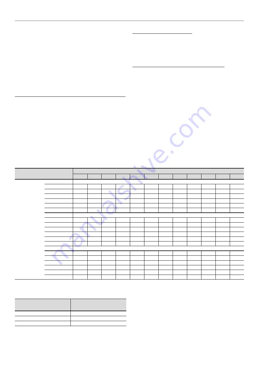
The table below gives the maximum period after which it is necessary to top up the inhibitors.
Maximum number of years between two corrosion inhibitor top-ups:
Total number of free cooling coils connected to the water loop
2
4
6
8
10
12
14
16
18
20
22
24
Total volume in
the loop* (litres)
Glycol 20%**
500
3
2
***
***
***
***
***
***
***
***
***
***
1000
6
3
2
2
***
***
***
***
***
***
***
***
2500
>15
8
5
4
3
3
***
***
***
***
***
***
5000
>15
>15
11
8
6
5
5
4
4
3
3
3
10000
>15
>15
>15
>15
>15
11
9
8
7
6
6
5
15000
>15
>15
>15
>15
>15
>15
14
12
11
10
9
8
Glycol 30%**
500
5
2
***
***
***
***
***
***
***
***
***
***
1000
10
5
3
2
***
***
***
***
***
***
***
***
2500
>15
12
8
6
5
4
***
***
***
***
***
***
5000
>15
>15
>15
>15
10
8
7
6
5
5
4
4
10000
>15
>15
>15
>15
>15
>15
14
12
11
10
9
8
15000
>15
>15
>15
>15
>15
>15
>15
>15
>15
14
13
12
Glycol 45%**
500
7
4
***
***
***
***
***
***
***
***
***
***
1000
14
7
5
4
***
***
***
***
***
***
***
***
2500
>15
>15
12
9
7
6
***
***
***
***
***
***
5000
>15
>15
>15
>15
>15
12
10
9
8
7
6
6
10000
>15
>15
>15
>15
>15
>15
>15
>15
>15
14
13
12
15000
>15
>15
>15
>15
>15
>15
>15
>15
>15
>15
>15
>15
*
Also check the minimum volume in the standard "application data" section.
** New EG or PG.
*** Volume too low.
Volume of inhibitor to add
after x* years, as a proportion
to the total volume in the loop:
Glycol 20%
0,8%
Glycol 30%
1,2%
Glycol 45%
1,8%
*
See previous table.
76
Summary of Contents for 30RB-170R
Page 2: ......
Page 51: ...11 13 Fan arrangement 11 MAIN COMPONENTS OF THE UNIT AND OPERATING CHARACTERISTICS 51...
Page 90: ......
Page 91: ......


