


CONTENTS (cont)
Page
Condenser Coils
. . . . . . . . . . . . . . . . . . . . . . . . . . . 60
• COIL CLEANING
Condenser Fans
. . . . . . . . . . . . . . . . . . . . . . . . . . . 60
Refrigerant Feed Components
. . . . . . . . . . . . . . 60
• ELECTRONIC EXPANSION VALVE (EXV)
• THERMOSTATIC EXPANSION VALVE (TXV)
(080-110 ONLY)
• MOISTURE-LIQUID INDICATOR
• FILTER DRIER
• LIQUID LINE SOLENOID VALVE
• LIQUID LINE SERVICE VALVE
Thermistors
. . . . . . . . . . . . . . . . . . . . . . . . . . . . . . . 65
• LOCATION
• TO REPLACE THERMISTOR T2 (Cooler)
• TO REPLACE THERMISTORS T1, T5, T6, T7,
AND T8
• THERMISTORS T3 AND T4
• THERMISTOR/TEMPERATURE
SENSOR CHECK
Safety Devices
. . . . . . . . . . . . . . . . . . . . . . . . . . . . . 67
• COMPRESSOR PROTECTION
• LOW OIL PRESSURE PROTECTION
• CRANKCASE HEATERS
• COOLER PROTECTION
Relief Devices
. . . . . . . . . . . . . . . . . . . . . . . . . . . . . 68
• HIGH-SIDE PROTECTION
• LOW-SIDE PROTECTION
• PRESSURE RELIEF VALVES
Other Safeties
. . . . . . . . . . . . . . . . . . . . . . . . . . . . . 68
START-UP CHECKLIST
. . . . . . . . . . . . . . CL-1 to CL-4
INTRODUCTION
These instructions cover installation, start-up, and service
of 30GT080-420 Flotronic™ liquid chillers with electronic
controls and units with factory-installed options (FIOPs).
Chillers are equipped with electronic expansion valves (EXV)
as standard. Conventional thermostatic expansion valves (TXV)
and liquid line solenoid valves are included as options on
30GT080-110 units only (NOT on associated modular units).
Differences in quick test procedures and operation se-
quences between the standard and optional units should be
carefully noted when following these instructions.
NOTE: Unit sizes 230-420 are modular units which are shipped
in separate sections as modules A and B. Installation direc-
tions specific to these units are noted in these instructions.
For modules 230B-315B, follow all general instructions as
noted for unit sizes 080-110. For all remaining modules, fol-
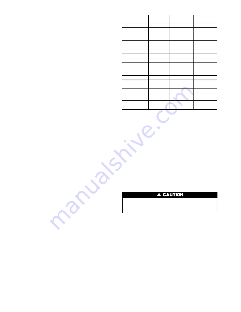
low instructions for unit sizes 130-210. See Table 1 for a
listing of unit sizes and modular combinations.
Inspect the unit upon arrival for damage. If damage is found,
file a claim right away with the shipping company. When
considering location for the unit, be sure to consult National
Electrical Code (NEC, U.S.A.) and local code requirements.
Allow sufficient space for airflow, wiring, piping, and serv-
ice. See Fig. 1-4. See Fig. 5 for optional non-fused discon-
nect location on 130-210, 230A-315A, and 330A/B-420A/B
units. Be sure surface beneath the unit is level, and is ca-
pable of supporting the operating weight of the unit. See
Fig. 6-8 and Tables 2A-3B for unit mounting and operating
weights.
NOTE: To facilitate refrigerant vent piping, unit sizes
130-210, 230A-315A, and 330A/B-420A/B will have fus-
ible plugs with
3
⁄
8
-in. SAE (Society of Automotive Engi-
neers, U.S.A.) flares if required by local codes.
Table 1 — Unit Sizes and Modular Combinations
UNIT MODEL
30GT
NOMINAL
TONS
SECTION A
UNIT 30GT
SECTION B
UNIT 30GT
080
80
—
—
090
90
—
—
100
100
—
—
110
110
—
—
130
125
—
—
150
145
—
—
170
160
—
—
190
180
—
—
210
200
—
—
230
220
150
080
245
230
150
090
255
240
150
100
270
260
170
100
290
280
190
110
315
300
210
110
330
325
170
170
360
350
190
190/
170*
390
380
210
190
420
400
210
210
*60 Hz units/50 Hz units.
INSTALLATION
Step 1 — Rig and Place the Unit —
These units are
designed for overhead rigging and it is important that this
method be used. Holes are provided in frame base channels,
marked for rigging (see rigging label on unit). It is recom-
mended that field-supplied 2-in. Schedule 40 steel pipes be
passed through these holes, extending beyond frame enough
to attach cables or chains on both sides for 080-110 and 230B-
315B units. All other units come with 6 lifting lugs. Use spreader
bars to keep cables or chains clear of unit sides. As further
protection for the coil faces, plywood sheets may be placed
against sides of unit, behind cables or chains. Run cables or
chains to a central suspension point so that angle from hori-
zontal is not less than 45 degrees. Raise and set unit down
carefully. See Fig. 6-8 for rigging centers of gravity.
1. Do not use forklift trucks on these units.
2. Modular (230-420) units MUST be rigged and placed
as separate sections.
For shipping, some domestic units and all export units are
mounted on a wooden skid under entire base of unit. Skid
can be removed before unit is moved to installation site. Lift
the unit from above to remove skid. See Fig. 6-8 rigging for
centers of gravity. On export units, the top skid can be used
as the spreader bars. If the unit is shipped with coil protec-
tion, it must be removed before start-up. The shipping bag
for export units must be removed before start-up. On export
units with a full crate, the crate sides must be removed to aid
in rigging.
If overhead rigging is not available, the unit can be moved
on rollers or dragged. When unit is moved on rollers, the
unit skid, if equipped, must be removed. To lift the unit, use
jacks at the rigging points. Use a minimum of 3 rollers to
distribute the load. If the unit is to be dragged, lift the unit
as described above, and place unit on a pad. Apply moving
force to the pad, and not the unit. When in its final location,
raise the unit and remove the pad.
Instructions continued on page 27.
2


