Carrier 09AZ091-182 Installation, Start-Up And Service Instructions Manual Download Page 2

2

GENERAL

These units are remote air-cooled condensers for use with

vertical package units, liquid chilling packages, or other air-

cooled compressor and remote condenser units. Models are

available for either vertical or horizontal airflow. The 09AZ

units have been optimized for use with the 30HX remote pack-

age units. Refer to Fig. 2 for model number nomenclature.

Units are remote air-cooled condensers with direct drive

axial flow condenser fan. These units are available in nominal

heat rejection capacity from 90 to 200 tons. Inlet and discharge

are on opposite sides of the unit. Units may be mounted in any

area having unobstructed air circulation. Low silhouette

permits installation on varied ground, roof, or suspended

applications.

Each unit consists of direct-drive motor(s), propeller fan(s),

fan guards, motor mounts, condenser coil with integral sub-

cooling circuit, and electrical junction box. Factory options that

extend the capability and features of the unit are available.

Check space requirements, service clearances, floor

strength, location of piping, size of power supply, and airflow

clearances before installing. See Fig. 3A and 3B for unit di-

mensions and Tables 1A and 1B for unit operating weights. See

Tables 2A and 2B  for corresponding chiller and condenser

sizes.

INSTALLATION

Step 1 — Complete Pre-Installation Checks —

Examine unit for damage incurred during shipment. File claim

immediately with transit company if damage is found. Check

the shipment for completeness. Verify that the nameplate elec-

trical requirements match the available power supply.

Step 2 — Rig and Place Unit

LOCATION — If roof installation is specified, make certain

that roof structure can support condenser weight. Refer to

Table 1.

Locate condenser where an adequate supply of inlet outdoor

air is available. Do not locate where the possibility of air recir-

culation exists, such as under a roof overhang. Locate in an

area free from airborne dirt or other foreign material that could

clog condenser units.
RIGGING — Leave the units in the carton or on the skid until

they are as close to the installation location as possible. The

method of rigging depends on the unit size. Never lift the unit

by the header or the return bends. Unit legs must be unbolted

and positioned while the unit is rigged.

The preferred method is with spreader bars from above the

unit. Lifting lugs are provided to aid in lifting the unit. Use

2-in. OD pipe and hooks in lifting eyes. Rig with 4 cables and

spreader bars. All panels must be in place when rigging. See

Table 3 and Fig. 4 for details concerning shipping weights, dis-

tance between lifting holes, center of gravity, and spreader bar

dimensions.

If overhead rigging is not possible, place unit on skid or pad

for rolling or dragging. When dragging, pull the pad. Do not

apply force to the unit. When in final position, raise from above

to lift unit off skid.

PLACING UNIT — The 09AZ units are designed for outdoor

applications. If the unit is mounted indoors, provisions must be

made to ensure that discharge air is not recirculated into the

unit. If the unit is ducted, the duct must not add more than

0.1 in. wg to the static pressure imposed on the fans.

Vertical units 09AZV should be located no closer than the

width of the unit to an obstruction such as a wall or another

unit. Keep the area around each unit clear to avoid restricting

the airflow to the unit. There must be 4 ft for service and for

unrestricted airflow on all sides of the unit and a minimum of

8 ft clear air space above units. For multiple units, allow 8 ft

separation between units for airflow and service.
MOUNTING UNIT — Units must be level to ensure proper

drainage of liquid refrigerant and oil. When units are installed

on a roof, they must be mounted on support beams that span

load walls. Ground mounted units should be installed on con-

crete pads of sufficient size to prevent grass and brush from

blocking the unit inlet. When unit is level and in proper loca-

tion, use mounting holes in legs for securing unit to supporting

structure. Fasteners for mounting unit must be field supplied. If

unit is to be mounted on vibration isolators, use mounting holes

in bottom of support legs as support points, and locate isolators

at those points.

Step 3 — Complete Refrigerant Piping — 

Refer to

Fig. 5 for typical piping details.
GENERAL — All field leak and pressure testing should be in

accordance with local code requirements. If no local code ex-

ists, follow American National Standards Institute (ANSI),

American Society of Heating, Refrigeration and Air Condition-

ing Engineers (ASHRAE) Safety Standard 15, latest revision.

For leak testing procedures, refer to the Carrier Refrigerant

Service Techniques manual. Perform Phos-copper brazing on

all field-made connections while protecting adjacent points

from heat.
COIL CIRCUITING — The  09AZV091-181  single  circuit

models require field assembly of gas and liquid manifolds (see

Fig. 6). Dual circuit units require no field assembly and piping.

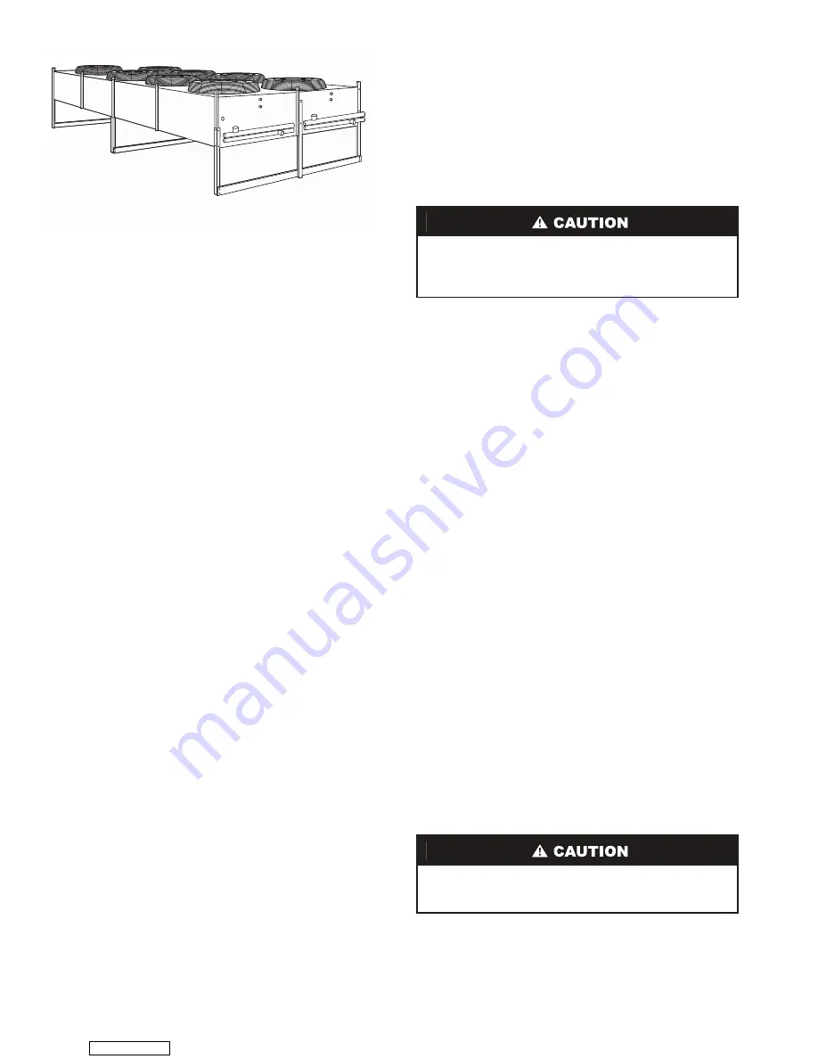
Fig. 1 — Typical 09AZ102 Unit

To avoid damage to units, do not forklift them unless they

are attached to skids designed for forklifting. Forklift

trucks used to lift units on skids must have forks a mini-

mum of 48 in. long.

To prevent unit damage, never connect two separate com-

pressor-evaporator circuits together on the same condenser

circuit.

Downloaded from 

ManualsNet.com

 search engine

Summary of Contents for 09AZ091-182

Page 1: ...d fire extinguisher nearby when brazing Use care in handling rigging and setting bulky equipment Separate power sources main and control power circuits are used for these units Be sure both main and control power circuits are disconnected before servicing Electrical shock could cause personal injury DO NOT USE TORCH to remove any component System contains oil and refrigerant under pressure To remo...

Page 2: ...ing weights dis tance between lifting holes center of gravity and spreader bar dimensions If overhead rigging is not possible place unit on skid or pad for rolling or dragging When dragging pull the pad Do not apply force to the unit When in final position raise from above to lift unit off skid PLACING UNIT The 09AZ units are designed for outdoor applications If the unit is mounted indoors provisi...

Page 3: ...th Contactors D Fan Cycling TEAO Circuiting Option A Single Circuit Subcooling E Dual Circuit Subcooling Factory Options A Aluminum Cabinet B Fused Disconnect D Aluminum Cabinet Fused Disconnect F Fused Disconnect 115 Volt Transformer Packaging 1 Standard Design Series 0 First Design V Ph Hz 1 575 3 60 3 208 230 1 60 5 208 230 3 60 6 460 3 60 Coil Construction Option Aluminum Fin Copper Tube C Cop...

Page 4: ... 3164 2590 4032 3110 3081 3730 3820 Shipping Weight 2705 3374 2800 4242 3370 3450 4040 4130 REFRIGERANT Type 134a FAN Type Direct Drive Vertical Discharge Quantity 8 10 8 10 10 12 12 12 Diameter in 26 26 26 26 26 26 26 26 No of Blades 4 4 4 4 4 4 4 4 Max Rpm 1140 1140 1140 1140 1140 1140 1140 1140 Total Airflow Cfm 124 000 155 000 124 000 155 000 155 000 186 000 186 000 186 000 Motor Hp 11 2 11 2 ...

Page 5: ...YP 194 1 4 96 TYP 1 1 8 TYP 15 6 6 242 1 4 48 96 TYP 1 1 8 TYP 15 CONTROL PANEL RETURN BEND COVER LIFTING HOLE 1 1 2 DIA TYP 6 290 1 4 96 TYP 1 1 8 TYP 15 6 IN DISCHARGE GAS 3 1 8 DIA LIQUID 2 5 8 DIA AIRFLOW 47 000 60 20 20 20 09AZV 1 A Single Circuit NOTES 1 Service clearances must be at least 48 in on all sides 2 Field assembly of discharge liquid headers required 09AZV091 101 09AZV151 09AZV171...

Page 6: ... 1 1 2 DIA TYP 194 1 4 96 TYP 1 1 8 TYP 6 6 242 1 4 48 96 TYP 1 1 8 TYP CONTROL PANEL RETURN BEND COVER LIFTING HOLE 1 1 2 DIA TYP 6 290 1 4 96 TYP 1 1 8 TYP 6 6 IN 46 DISCHARGE GAS 2 5 8 DIA DISCHARGE GAS 2 5 8 DIA 94 LIQUID 2 1 8 DIA LIQUID 2 1 8 DIA AIRFLOW 6 5 5 6 6 5 5 09AZV 2 E Dual Circuit NOTE Service clearances must be at least 48 in on all sides 09AZV102 122 09AZV112 132 142 09AZV162 172...

Page 7: ...02 605 467 462 560 573 H 308 373 377 316 403 311 308 373 382 1 2 LEG BOLTS Fig 4 Unit Rigging A ROTATE UNIT FLAT 1 Gently pull top of unit over maintaining cable tension as unit is rotated from vertical to horizontal position B LOWERING LEGS INTO POSITION 1 Reattach lifting hooks into lifting eyes in the perma nently attached leg channels One set of hooks at each leg position 2 Remove the four 1 2...

Page 8: ...nual Part 3 or the Carrier E20 II Software Refrigerant Piping program for proper piping sizes and design 4 Hot gas lines should rise above refrigerant level in condenser circuit 5 Trap should be installed on hot gas lines to prevent condenser oil and refrigerant vapor migration from accumulating on com pressor heads during off cycle 6 For piping lengths greater than 50 ft 15 2 m provide support to...

Page 9: ...ing speed control head pressure control winter start control fan cycling and electrical interlock may affect wiring connec tions Refer to Fig 7 9 for typical unit wiring 1 Power entry is at one end only 2 Fan motors are thermally protected All 3 phase motors are protected against primary single phasing conditions 3 Replacement of factory wires must be with appliance wiring material rated 105 C or ...

Page 10: ...5 1 60 09AZV SIZE 208 230 3 60 460 3 60 575 3 60 CONTROL CIRCUIT V Ph Hz FLA MCA MOCP Min Max Volts FLA MCA MOCP Min Max Volts FLA MCA MOCP Min Max Volts 102 6 5 53 6 60 0 187 253 3 3 27 2 30 0 414 506 2 4 19 8 20 0 518 632 115 1 60 112 6 5 66 0 70 0 187 253 3 3 33 8 35 0 414 506 2 4 24 6 25 0 518 632 115 1 60 122 6 5 56 3 60 0 187 253 3 3 27 2 30 0 414 506 2 4 19 8 20 0 518 632 115 1 60 132 6 5 6...

Page 11: ...60 C copper conductors only 2 See nameplate for branch circuit fuse size use time delay fuse only 3 Motors 1 and 2 are located at header end of unit 4 All wire is 14 ga except as noted C Contactor FB Fuse Block MTR Motor Downloaded from ManualsNet com search engine ...

Page 12: ...tor FB Fuse Block NOTES 1 Use 60 C copper conductors only 2 See nameplate for branch circuit fuse size use time delay fuse only 3 Motors 1 and 2 are located at header end of unit 4 All wire is 14 ga except as noted Downloaded from ManualsNet com search engine ...

Page 13: ...the key 6 Replace the permagum sealing material and the rubber cap over the end of the motor shaft to prevent moisture from causing fan to rust on the shaft 7 Replace the fan guard Fan Motor Removal 1 Make certain condenser power is off 2 Remove fan guard and fan 3 Loosen nut on the motor holding clamp that secures mo tor to motor support 4 Lift motor upward Remove the fan wheel through the fan di...

Page 14: ...not operating correctly 1 Check head pressure control and be sure it is operating properly Install if not provided 2 Check wind baffles apply if required 3 Check operation of fan cycling control on two fan units Unit trips on low pressure at start up with low outdoor temperatures 1 Winterstart kit not installed or not working correctly 2 Fan cycling control for two fan units is not installed or no...

Page 15: ... TO CONFIRM PROPER DAINAGE Y N ________ ARE PROPER AIR FILTERS IN PLACE Y N ________ CONTROLS HAVE THERMOSTAT INDOOR FAN CONTROL AND CONDENSER FAN CONTROL RELAY WIRING CONNECTIONS BEEN MADE AND CHECKED Y N ________ ARE ALL WIRING TERMINALS including main power supply TIGHT Y N ________ HAS CRANKCASE HEATER IF EQUIPPED ON UNIT BEEN ENERGIZED FOR 24 HOURS Y N ________ 09AZ UNIT CHECK POWER SUPPLY DO...

Page 16: ...FTER AT LEAST 15 MINUTES RUNNING TIME RECORD THE FOLLOWING MEASUREMENTS OIL PRESSURE Where Appropriate ________ ________ SUCTION PRESSURE ________ ________ SUCTION LINE TEMP ________ ________ DISCHARGE PRESSURE ________ ________ DISCHARGE LINE TEMP ________ ________ ENTERING CONDENSER AIR TEMP ________ ________ LEAVING CONDENSER AIR TEMP ________ ________ EVAP ENTERING AIR DB dry bulb TEMP _______...

Reviews: