


3
When a shutdown situation occurs due to a high
motor or discharge temperature, 1CR, 2CR, LIQ,
UNL, and OIL outputs will all open while the ALM
output will close. The alarm LED will light along
with the corresponding failure LED (motor or
discharge). The module will reset when the motor
or discharge reaches the reset temperature and a
30-second delay is observed.
The motor 5K thermistor is located between S1
and S2 on the compressor electrical terminal
plate. In the event of a thermistor failure, a spare
thermistor is available between S3 and S2.
Attach S1 to the motor connection on the lower
left of the CEM. Connect S2 to the common port
just to the right of the motor connection on the
CEM. The discharge 5K thermistor has two wires.
Attach one wire to the discharge connection on
the lower left of the CEM. The other wire should
be connected to the same common port where
the motor 5K thermistor is attached. The
discharge 5K thermistor must be mounted on a
clean dry area of the discharge line as close to
the discharge service valve as possible. The
thermistor must then be wrapped with high
temperature insulation.
Should either 5K thermistor fail (open or short),
the compressor will be shut down with 1CR, 2CR,
LIQ. UNL, and OIL outputs all opening while the
ALM output closes. The alarm LED will light along
with the fault LED and the corresponding 5K
thermistor LED (motor or discharge).
The DC voltage can be measured across the
motor and, or discharge pins (motor to common
or discharge to common) and converted to
temperature. See the "Temperature vs. DC
Voltage" on the following page for the conversion.
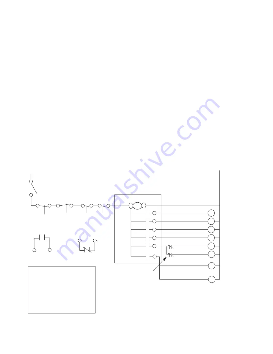
The connection where power is brought into the
module is found at port L1 located at the upper
left corner of the CEM. The module must be
wired last in series with the other mechanical
safeties (see CEM Wiring Diagram below). In
order to complete the circuit for the module, L2
(common) must be wired to the 240 or 115
connection, depending on the control voltage.
Detailed information on each CEM output is
shown on next page.
A VOLTAGE SENSING RELAY WITH NORMALLY OPEN CONTACTS
SHOULD BE WIRED TO THE LOAD SIDE OF THE COMPRESSOR
CIRCUIT BREAKER, WITH THE CONTACTS IN SERIES WITH THE
COMPRESSOR CONTROL CIRCUIT. THIS IS TO DEACTIVATE THE
CONTROL CIRCUIT IN CASE OF A BREAKER TRIP.
(CURRENT SENSING RELAY MAY BE USED FOR PROOF POINT.)
RACK CONTROLLER
CONTACTS
USE ALARM RELAY
SPARE CONTACTS
OPDS POWER
BREAKS ON CEM
FAULT
240 / 120
L2
1CR - ACROSS THE LINE START.
2CR - FOR PART WINDING START.
ALARM - SIGNALS COMPRESSOR
SHUTDOWN ON MOTOR OR DISCH
TEMP FAULT.
LIQUID - CONTROLS MOTOR
COOLING VALVE.
UNLOADER - DELAYS COMPRESSOR
LOADING FOR 45 SEC ON START.
OIL - CONTROLS COMPRESSOR OIL
SOLENOID, 2 SEC DELAY ON START.
INPUT TO RACK
CONTROLLER
ALARM RELAY
DPDT
LPS
VOLTAGE SENSING RELAY CONTACTS
HPS
RRPS
OPDS
L1
240 OR
115 VOLT
1CR
2CR
ALM
LIQ
ECONOMIZER SOLENOID COIL
OIL SOLENOID COIL
VI SOLENOID COIL
UNLOAD SOLENOID COIL
MOTOR COOLING COIL
ALARM RELAY (DPDT)
(FOR PART WINDING START)
CONTACTOR COIL
L1
COMMON (L2)
UNL
OIL
CEM WIRING DIAGRAM


