


3.5 Oil Pressure Protection
Current Carlyle compressor design requires
that oil is fed to the compressor at discharge
pressure. The pressure differential between oil
pressure (discharge pressure-oil pressure drop)
and suction pressure is used to drive oil
through the compressor. There cannot be any
excessive flow restrictions (excessive pressure
drop across oil filters, etc...) in the oil system to
ensure adequate lubrication. There must be
sufficient oil pressure differential between the
oil pressure and the suction pressure to drive
the lubricant through the compressor.
The LonCEM protection module (available mid-
year 2000) provides comprehensive oil pres-
sure protection through the use of discharge
pressure, oil pressure and suction pressure
transducers to monitor operating pressures.
Appendix A contains a complete description of
the application and operation of the LonCEM
module. Refer to the following table for a sum-
mary of LonCEM parameters for alarms (indi-
cate system problems and allow the compre-
sor to continue operating) and cut-outs (caus-
es compressor to shut down and requires
manual reset).
Refer to Appendix B for information regarding
the oil protection system used with the Carlyle
Electronic Module (CEM) prior to midyear
2000.
3.6 Oil Solenoids
A normally closed solenoid is required in the oil
feed line to each compressor, located before
(upstream of) the high side of the Oil Pressure
Differential Switch (OPDS).
To avoid exces-
sive pressure drop, the internal port size
must be 5/16" diameter or larger.
An oil
strainer is required before each oil solenoid (or
as an integral part of the solenoid). The sole-
noid will protect the compressor from being
filled with oil from the high pressure oil feed line
during the off cycle. Each solenoid must be
properly wired to the Carlyle CEM
(per installation instructions) of the compressor
it is controlling. The valve must be open during
the on cycle and closed during the off cycle.
Manually adjustable valves must be
checked to ensure the manual operation
stem is completely back seated (ensuring
the valve is closed when the solenoid is
de-energized).
Carlyle does offer a combina-
tion oil control solenoid valve and sight glass
assembly (EF23ZZ025) which incorporates a
solenoid valve.
Warning!
When testing the control circuit without the
compressor running, the oil line must be valved off
so that the compressor will not be filled with oil
.
Whenever possible use control logic to deter-
mine that the compressor is actually running
before opening the oil solenoid. There are
two ways to accomplish this:
1. Make sure the current is greater than zero
and less than the locked rotor amperage
(LRA).
2. Make sure the discharge plenum pressure
is greater than the suction pressure (this
method is ineffective on multiple com-
pressor racks).
13
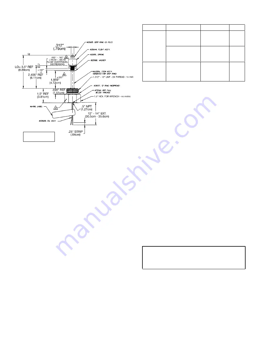
OIL LEVEL SWITCH DIMENSIONS
FOR REFERENCE ONLY
INCHES
[CENTIMETERS (cm)]
Parameter
Explanation
Alarm/Cut-Out
Reset
Discharge pressure
– oil pressure is
greater than 35 psi
(2.4bar)
Alarm
Auto
Oil system
Pressure
Drop
Discharge pressure
– oil pressure is
greater than 50 psi
(3.4bar)
Cut-Out
Manual
Oil Pressure
Differential
Oil pressure –
suction pressure is
less than 45 psi
(3.0bar) for 90
seconds or more
Cut-Out
Manual


