CARLO GAVAZZI RSGD Manual Download Page 15


15 


Alarm Reset 

The alarm reset mode can be: 


AUTO


MANUAL 


Motor Overload Alarm

 & 

Phase Sequence Alarm 

The motor overload and phase sequnce can be: 


ENABLE


DISABLE 


Remote Reset

 &

 PTC 

The remote reset and PTC can be: 


OPEN


SHORT 
 

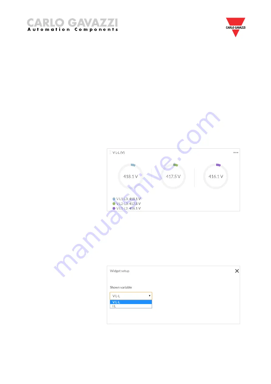
c.  Voltage & Current Monitoring 


This function monitors either one of the following variables: 

  Line-to-Line voltage (V) 

  Line current (A) 

To select between the aforementioned variables, you must click on the 
upper  right-hand  corner  of  the  widget  and  the  following  screen  will 
appear: 


Summary of Contents for RSGD

Page 1: ...RSGD 75mm Modbus Protocol Rev 2 0...

Page 2: ...to one communication 8 3 4 One to many communication 9 3 5 Automatic Connection 10 3 6 Manual Connection 11 Chapter 4 SCS User Interface 4 1 Software structure 12 4 2 Toolbar icons 12 4 3 Dashboard wi...

Page 3: ...nstruction manual carefully If the product is used in a way not specified by the producer the protection provided by the product may be impaired 1 3 Precautions For your safety the following symbol is...

Page 4: ...f the PC meets the above system requirements you can download the latest version of the setup_SCS_2 0 zip from our website http gavazziautomation com nsc HQ EN soft_starters 2 2 Installing the softwar...

Page 5: ...Software Choose a location to install the software or click next to continue with the default location Click next to start the installation Once the installation is complete you should see the Carlo...

Page 6: ...les installed by SCS will be removed from your PC The following steps instruct you to uninstall the software from your PC Open the Control Panel in Windows and under Programs click on Uninstall a prog...

Page 7: ...ation parameters can be modified 3 2 Installation In order to be able to establish communication between a PC or a controller and the RSGD you will need to connect a raw cable between the communicatin...

Page 8: ...tion the RSGD unit must be first powered up with the specified supply voltage If the supply LED is green fixed on the soft starter you can establish communication with the soft starter The software pr...

Page 9: ...mmunication with the soft starter The software provides two methods to establish one to many communication a Automatic connection more details in section 3 5 b Manual connection more details in sectio...

Page 10: ...The software starts to find all the devices attached to the serial port If connection is successful the following window will appear if you have established communication In the event that communicati...

Page 11: ...arameters and click on the Connect icon If connection is successful the following window will appear if you have established communication In the event that communication is not established the follow...

Page 12: ...icons in the toolbar in order to choose among the main windows of the software Toolbar icons Icon Description Open the Dashboard window Open the Settings window Open the Variables window Navigate to a...

Page 13: ...h the software from the Settings window under the Inputs section If this command is ON as soon as the soft starter resets from an alarm the load will switch ON Refresh command When Start Command Refre...

Page 14: ...whether or not the soft starter is in alarm condition Status of Top of Ramp Relay This variable indicates whether or not the soft starter is in bypass mode Status of Run Relay This variable indicates...

Page 15: ...BLE DISABLE Remote Reset PTC The remote reset and PTC can be OPEN SHORT c Voltage Current Monitoring This function monitors either one of the following variables Line to Line voltage V Line current A...

Page 16: ...r Power factor PF Power kWh To select between the aforementioned variables you must click on the upper right hand corner of the widget and the following screen shall appear e Temperature Monitoring Th...

Page 17: ...wing screen shall appear f Scope This function works the same way as an oscilloscope and it can monitor either one of the following variables Line to Line voltage V Line current A To select between th...

Page 18: ...oftstarter will not respond to a start command if it is in Alarm state h Sales Engineering The following variables and settings are password protected Junction Temperature o C Virtual Motor Temperatur...

Page 19: ...ock these variables and settings you must enter the correct access code The access code can be obtained from Carlo Gavazzi sales support If the access code is incorrect the following message will be d...

Page 20: ...e sure that the RSGD is in idle state while parameters are modified The functions provided by the Settings window are a Delays This function contains the delays related to stop to start and start to s...

Page 21: ...alarm limits c Communication In this function the user can visualise and modify the communication parameters The default communication parameters can be found in Chapter 3 Section 3 1 The communicati...

Page 22: ...so enable disable the Start Command Refresh a k a heartbeat signal The factory default Control Mode is set to A1 A2 mode If the Start Command Refresh is disabled the load remains switched ON in case c...

Page 23: ...or CSV csv format which contains information about the last 32 starts performed For further information on the content of the history file we advise you to contact Carlo Gavazzi sales support g Reset...

Page 24: ...4 5 Variables window The Variables window lists the instantaneous variables and the counters available for the RSGD units The functions provided by the Variables window are a Power Monitoring b Operat...

Page 25: ...25 c Voltage Monitoring d Current Monitoring e General Counters...

Page 26: ...arter will trip Shorted SCR In case the RSGD detects that there is a damaged shorted thyristor SCR on any of the three phases the soft starter will trip Wrong Phase Sequence If the connection to the s...

Page 27: ...ered This condition can be triggered by too many starts per hour an over load condition during starting and or stopping or a high surrounding temperature Overload The overload alarm can be triggered i...

Page 28: ...gisters 04h This function code is used to read the contents of a 1 input register word The request frame specifies the starting register address and the number of registers to be read The register dat...

Page 29: ...th Value Note Physical Address 1 byte 1h to F7h 1 to 247 Function Code 1 byte 06h Starting Address 2 bytes 0000h to FFFFh Byte order MSB LSB Quantity of Registers N word 2 bytes 0000h to FFFFh Byte or...

Page 30: ...efer to Appendix Alarm Counters Lists the number of times a particular alarm has occurred General Counters Includes counters related to operational use Instantaneous Voltage and Current Lists the inst...

Page 31: ...rrent limit x10 332776 8007h 1 System Voltage UINT16 System voltage x10 Device Status Read only mode function 04h Modicon Address Physical Address Length words Description Data Format Notes Scaling Fa...

Page 32: ...No action 0001h Reset alarm Control Read only mode function 04h Modicon Address Physical Address Length words Description Data Format Notes Scaling Factor 328673 7000h 1 Control Mode UINT16 Control Mo...

Page 33: ...s UINT16 Time from Last Stop x1 336868 9003h 1 Time from Last Start s UINT16 Time from Last Start x1 Write only mode function 06h Modicon Address Physical Address Length words Description Data Format...

Page 34: ...4 starts present in history x1 349157 C004h 64 Start 17 to Start 20 UINT16 Data of the fifth set of 4 starts present in history x1 349158 C005h 64 Start 21 to Start 24 UINT16 Data of the sixth set of...

Page 35: ...16 Number of power up x1 316394 4009h 1 Number of power down UINT16 Number of power down x1 Instantaneous Voltage and Current Variables Read only mode function 04h Modicon Address Physical Address Len...

Page 36: ...n Data Format Notes Scaling Factor 312545 3100h 1 Poutput kW UINT16 Average active power output x10 312546 3101h 1 Qoutput kVAr UINT16 Average reactive power output x10 312547 3102h 1 Soutput kVA UINT...

Page 37: ...how the user can change the communication parameters of the RSGD unit Step 1 Go to the Settings window Step 2 Click on the Communication settings Step 3 Change the communication parameters as desired...

Page 38: ...stop the RSGD unit through Modbus Step 1 Go to the Settings window Step 2 Click on the Inputs settings set the Control Mode to Modbus Mode and click save Step 3 Go to the Dashboard window and start t...

Page 39: ...the RSGD unit using force refresh signal Step 1 Go to the Settings window Step 2 Click on the Inputs settings set the Control Mode to Modbus Mode enable the Start Command Refresh set the Refresh Inter...

Page 40: ...40 Step4 During the Refresh Interval click on the Refresh Command button so that the load remains on Step 5 Do not click on the Refresh Command button when you want to stop the load...

Page 41: ...MSB2 LSB16 MSB16 All data received is expressed in hexadecimal Example Read the data of the last 32 starts recorded in the RSGD memory Step 1 Read data from address C000h Request Frame Description Va...

Page 42: ...Function Code 84h Exception Code 01h 02h 03h CRC Step 2 Divide the received data into four blocks of 32bytes of data Start 1 0100AF8741020F910080300800009904000000000000750C0080200848490020h Start 2 0...

Page 43: ...ax IL3 during ramp up The maximum current measured on phase 3 during ramp up P HP mode Indicates if start was done in HP Q Time to reach full speed The time duration that the motor took to reach full...

Page 44: ...ax IL3 during ramp up 2A P 0 0 HP mode 0 Q 0 x0 001 0 000 Full speed reached at 0 000s R 1177 x0 001 1 177 Cont current reached at 1 177s S 0 0 Max IL1 during bypass 0A T 0 0 Max IL2 during bypass 0A...

Page 45: ...store the result in variable Convert to decimal and store the result in variable Conversion result Value System Voltage V Phase Sequence 10 220 ve ph seq 11 220 Undefined 12 220 ve ph seq 19 400 ve p...

Page 46: ...SB3 to binary bitwise AND by 0b00100000 and store the result in variable Right arithmetic shift by 5 and store the result in variable Convert to decimal and store the result in variable Conversion res...

Page 47: ...e M N Format LSB5 MSB5 Bits 64 65 66 67 68 69 70 71 72 73 74 75 76 77 78 79 Code N O P Format LSB6 MSB6 Bits 80 81 82 83 84 85 86 87 88 89 90 91 92 93 94 95 Code Variable Conversion Statement Comments...

Page 48: ...mat LSB7 MSB7 Bits 96 97 98 99 100 101 102 103 104 105 106 107 108 109 110 111 Code Variable Conversion Statement Comments Q Time to reach full speed Convert MSB7 to decimal multiply by 256 and store...

Page 49: ...ble Conversion result N A T Max IL2 during bypass Convert MSB9 to binary bitwise AND by 0b00111111 left arithmetic shift by 4 and store the result in variable Convert LSB10 to binary right arithmetic...

Page 50: ...80 181 182 183 184 185 186 187 188 189 190 191 Code Variable Conversion Statement Comments W Ramp down duration Convert MSB12 to decimal multiply by 256 and store the result in variable Convert LSB12...

Page 51: ...and store the result in variable Conversion result N A Z Max IL3 during ramp down Convert LSB14 to binary bitwise AND by 0b00001111 left arithmetic shift by 6 and store the result in variable Convert...

Page 52: ...able Conversion result Value State 0 Internal fault 1 Spare 2 Spare 3 Short circuit during idle 4 Short circuit during ramp 5 Spare 6 Negative phase sequence 7 Spare 8 Spare 9 Synchronisation loss 10...

Reviews: