21
ENGLISH
20
ENGLISH
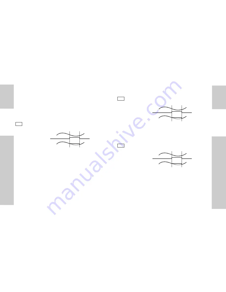
F4 : A/B, frequency (speed) ratio mode
The instrument measures the frequency of input A and input B and
executes the following calculation: display=(Fa/Pu.1*PS.1)/(Fb/
Pu.2*PS.2). This measuring capability is ideal for monitoring the relative
speeds of shafts, conveyor belts and other moving machinery.
F5 : B/(A+B)*100
The instrument measures the frequency of input A and input B and
executes the following calculation: display=(Fb/Pu.2*PS.2)/[(Fa/
Pu.1*PS.1)+(Fb/Pu.2*PS.2)]*100. This measuring capability is used in
all the applications where it is necessary to measure a mixture flow
between two liquids. If the instrument is equipped with an analogue
output, this signal can be transmitted to a paper recorder to show the
HOLD
Input
Input B/(A+B)
Display
HOLD
Input
Input A/B
Display
Pu.2*PS.2). This result represents the difference between the input
channels and can be used when the speed difference between two
conveyor belts has to be as low as possible without considering the
reference speed of the first conveyor (in any case within a well known
value that can be controlled by the available alarm set-point) in order to
avoid any transportation problem of the produced goods.
F3 : (A - B)/B*100, frequency (speed) error ratio
The instrument measures the frequency of input A and input B and
executes the following calculation: display=[(Fa/Pu.1*PS.1)-(Fb/
Pu.2*PS.2)]/(Fb/Pu.2*PS.2)*100. This result represents the relative
error between the 2 input channels; this measuring capability is used
when the speed difference between two conveyor belts has to be as low
as possible in any case within a well known value that can be controlled
by the available alarm set-points. If the instrument is equipped with the
analogue output, this signal can be used to correct the speed of the
second conveyor belt.
HOLD
Input
Input (A-B)/B
Display
Summary of Contents for MDI 40 TF - CONFIGURATION SOFTWARE
Page 1: ......


