background image

32

Technical features

Interface modules

27

Serial port connections

34

38

■ 

Number of inputs

Current: 3
Voltage: 4

■ 

Accuracy

Display,  RS422/ 485:

Ib: 5A, Imax: 10A; Ib: 20A, Imax: 90A

Current

: from 0.003Ib to 0.2Ib: ±(0.5%RDG +3DGT); 

from 0.2Ib to Imax: ±(0.5%RDG +1DGT).

Voltage:

in the Un range: ±(0.5% RDG + 1DGT).

Frequency:

±0.1% RDG (50 to 60 Hz).

Active power:

(@ 25°C ± 5°C, R.H. 

90%): 

±1% RDG ±1DGT (PF 1, 0.1Ib to Imax, in the Un range; 
PF 0.5L,  PF 0.8C, 0.2Ib to Imax, in the Un range).

Energies:

(@ 25°C ± 5°C, R.H. 

90%): Class 1 according to

EN61036; Class 2 according to EN61268; Ib: 5A, Imax: 10A 0.1Ib:
500mA start-up current: 20mA; Ib: 20A, Imax: 90A 0.1Ib: 2A start-
up current: 80mA. “Un” see “Rated input voltages (Un)/range”

■ 

Additional errors

According to EN61036, EN61268.

Wave form:

<1% (3rd harmonic: 10%).             

Voltage asymmetry:

< 0.5% (with reference to Un).

Magnetic induction:

0 (up to 0.5 mT).

HF electromagnetic fields

: < 1% 

Influence of accessories:

0.

■ 

Temperature drift

200ppm/°C.

■ 

Sampling

1000 samples/s at 50Hz.

Display

Type:

back-lighted LCD.

Display of instantaneous variables:

4x3

1

/

2

DGT.

Energies: total meters:

8 DGT +7

1

/

2

DGT;

partial meters

:

8 DGT +7

1

/

2

DGT.

Summary of Contents for EN61036

Page 1: ...working experience of many decades and a widespread presence all over the world All this because we want our customers to have the top service and the top products Welcome in the Carlo Gavazzi world...

Page 2: ...he energy meters menu 11 The functions of the energy meters submenu 11 Digital outputs 14 Digital output 1 14 Alarm digital output 15 Digital output 2 16 RS422 485 Serial communication port address 16...

Page 3: ...ent In order to achieve the best results with your instrument we recom mend you to read this instruction manual carefully HOW TO USE THE SYMBOLS Go to the page where the previous main subject is descr...

Page 4: ...and description of displayed measuring pages When the instrument is switched on it displays the first measuring page relating to the kWh and kvarh total meters as shown in the picture on the top of th...

Page 5: ...present and the instrument is set on tot prd The tariffs are managed by set ting the digital inputs as shown in the table on page 13 When digital input modules are present and the instrument is set on...

Page 6: ...g to phase 3 It displays the W active power relating to phase 2 It displays the W active power relating to phase 1 When digital input modules are present and the instrument is set on tot 2 Cn it displ...

Page 7: ...d 1 2 3 shows its phase See Useful information on page 20 The scrolling of the measuring pages is cyclic at the end of the cycle you go back to the first page on the left Access to the main menu From...

Page 8: ...ect the value of the CT ratio Example if the CT primary cur rent transformer has a current of 300A and the secondary has a current of 5A the CT ratio corre sponds to 60 that is 300 5 Choose the Ct rAt...

Page 9: ...the VT ratio corresponds to 200 that is 20000 100 Choose the Vt rAtio function by means of the and to enter the menu press then select the desired value by means of the and keys and confirm it with S...

Page 10: ...minutes SYNCHRONISATION OF THE POWER DMD CALCULATION The calculation can be synchronized in two different ways without DIGITAL INPUT module the reset and the beginning of the SYNCHRONISATION is car r...

Page 11: ...the energy meters that will be described in detail below S The submenu of the energy meters with the relevant functions is only available if the digital input module is present if not the instrument d...

Page 12: ...t 2 Cn it enables the combina tion of total meters and Water and Gas counters see also Display pages on page 6 Once the PrESCAL C 1 has been selected enter by means of the keys the weight of every pul...

Page 13: ...ng table For the connections of the AO2940 digital input module see page 26 INSTRUMENT MODE tot Prd mode Display of total and partial multitariff meters tot 1 Cn mode Display of total and day night ti...

Page 14: ...pulses see table on page 19 by means of the and keys and confirm the value with rEA EnE enable the retransmis sion of the reactive energy by means of pulses Confirm it with and then set the number of...

Page 15: ...the value of the W dmd variable by means of the keys and confirm with oFF off alarm set point It s the Wdmd value over which the alarm is deactivated Select the Wdmd value by means of the keys and con...

Page 16: ...keys and confirm the value with rEA EnE enables the retransmis sion of the reactive energy by means of pulses Confirm it with and then set the number of pulses see table on page 19 by means of the key...

Page 17: ...to carry out the command S S S S RESET To measur ing mode Reset of partial meters Select rESEt Prt from the main menu by means of the keys then confirm with when the instrument asks for the reset you...

Page 18: ...Slot B 1 2 ON 1 2 The variables measured by the instrument are correct if the polarities of the inputs have been observed as shown in the figure below if not measuring and retransmission errors may oc...

Page 19: ...l n o A 0 9 0 2 n o i s r e v 4 M E o i t a r T V o i t a r T C h W k s e s l u p e g n a R h r a v k m o r F o T m o r F o T 1 5 0 0 5 1 0 0 0 1 h r a v k h W k s e s l u p the VT because the program...

Page 20: ...es The Err message The instrument takes the measure only for quadrants 1 and 4 consumed energy The active energy is obtained by integrat ing only the sum of the phase active powers on quadrants 1 and...

Page 21: ...IS IMPORTANT that the instrument is switched off when you plug in or disconnect the optional modules For SAFETY reasons in the 20 90 A version the tighten ing torque value of the current terminals mus...

Page 22: ...remove the front cover Press Press Press Press To remove the front cover of EM4 DIN press contempora neously the four release levers at the four angles of the instrument as shown above Auxiliary power...

Page 23: ...Relay output open collector output AO2910 AO2940 digital inputs AR2950 RS422 485 Serial port AO2900 open collector output AR2950 RS422 485 SERIAL PORT AO2940 DIGITAL INPUTS It shows the posi tion whe...

Page 24: ...screwdriver Connection label Identification label To remove the modules use a screwdriver Insert the screw driver in the slot on the side of the removable modules as indicated in the figure above Use...

Page 25: ...anel mounting Access to programming ALLOWED See also Useful information on page 18 To configure the instrument correctly it is impor tant to verify that dip switch 1 is in OFF position See figure abov...

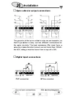
Page 26: ...connections The grounds of the open collector outputs are separate so that it s possible to carry out two different connections for the same module The load resistance Rc must have a value the makes...

Page 27: ...wire connection 4 wire connection The termination of the serial port is carried out only on the last instrument of the network by means of a jumper connection between RX and T The 4 wire connection i...

Page 28: ...t connection with neutral 3 phase system Unbalanced load Auxiliary power supply Self power supply LOAD Fig 2 Direct connection without neutral 3 phase system Unbalanced load Fig 3 Direct connection wi...

Page 29: ...diagrams Self power supply Auxiliary power supply LOAD Fig 5 Direct connection with without neutral 3 phase system Unbalanced load Auxiliary power supply LOAD Fig 6 CT connection with neutral 3 phase...

Page 30: ...ARON CT connec tion without neutral 3 phase system Unbalanced load Auxiliary power supply LOAD Fig 8 CT ARON and VT connection without neutral 3 phase system Unbalanced load Auxiliary power supply LOA...

Page 31: ...ary power supply LOAD Fig 10 CT and VT con nection without neutral 3 phase system Unbalanced load Auxiliary power supply LOAD Fig 11 CT and VT con nection without neutral 3 phase system Unbalanced loa...

Page 32: ...nge Energies 25 C 5 C R H 90 Class 1 according to EN61036 Class 2 according to EN61268 Ib 5A Imax 10A 0 1Ib 500mA start up current 20mA Ib 20A Imax 90A 0 1Ib 2A start up current 80mA Un see Rated inpu...

Page 33: ...5 10 A permanent 10A at 50Hz 20 90 A for 10ms 2700A max at 50Hz 20 90 A permanent 90A at 50Hz Voltage overload Permanent 1 2 Un For 1s 2 Un Rated input voltages Un range AV0 208VL L 20 90 AAC Un 20 1...

Page 34: ...writing only all the configuration parameters ener gy reset activation of static output Energy storing EEPROM max 99 999 999 kWh kvarh Data format 1 start bit 8 data bit no parity 1 stop bit Baud rate...

Page 35: ...00 ms Type open collector NPN transistor VON 1 2 VDC max 100 mA VOFF 30 VDC max Insulation AO2900 module by means of optocouplers 2000 VRMS between outputs and measuring inputs 2000 VRMS between outpu...

Page 36: ...ing data 1st level Password 0 no protection 2nd level Password from 1 to 1000 all data are protected Transformer ratio CT from 1 to 5000 VT from 1 0 to 199 9 and from 200 to 1999 Note the CT VT ratio...

Page 37: ...sulation 2000 VRMS between inputs outputs and earth Dielectric strength 4000 VRMS for 1 minute Rejection CMRR 100 dB 48 to 62 Hz EMC burst 4kV level 4 EN61000 4 4 Radiated electromagnetic fields 10V m...

Page 38: ...ORYL PC self extinguishing UL 94 V 0 Mounting DIN rail and wall mounting Protection degree front IP40 connections IP20 Weight 800 g approx packing included Note the pictures in the manual refer to an...

Page 39: ...al number Password Instrument s settings Pulse value for gas meters water Pulse value for kWh meters kvarh CT ratio VT Serial address Integration time min Tariffs t1 from to t2 from to t3 from to t4 f...

Page 40: ...40 User s page 35 Digital inputs 39...

Reviews: