background image

24

EM530/EM540 - User manual | CARLO GAVAZZI Controls SpA

Cleaning

To keep the display clean, use a slightly wet cloth. Never use abrasives or solvents.

Responsibility for disposal

Dispose of the unit by separately collecting its materials and bringing them to the facilities specified by government 

authorities or by local public bodies. Proper disposal and recycling will help preventing potentially harmful consequences 

for the environment and for people.

Summary of Contents for EM530DINAV23XM1PFA

Page 1: ...EM530 EM540 Energy analyzer for three phase and two phase systems USER MANUAL...

Page 2: ...easurement pages 10 Working with the SETTINGS menu 10 Working with the INFO menu 10 Working with the RESET menu 10 Commissioning 11 Preliminary settings 11 MID SETTINGS menu 11 QUICK SETUP menu 12 Men...

Page 3: ...the RESET menu 20 Restoring the MID menu using the RESET menu 21 WIRING CHECK function 22 Introduction 22 Display check 22 Check from UCS software 22 Virtual correction from UCS software or UCS Mobile...

Page 4: ...working life It should be consulted for all situations tied to configuration use and maintenance For this reason it should always be accessible to operators NOTICE no one is authorized to open the an...

Page 5: ...he unit can be equipped according to the model with a static output pulse or alarm a Modbus RTU communication port or an M Bus communication port Description EM530 Front Area Description A Voltage inp...

Page 6: ...connection up to 65 A Digital output x EM540DINAV23XS1X Direct connection up to 65 A RS485 Modbus RTU x EM540DINAV23XM1X Direct connection up to 65 A M Bus x EM540DINAV23XO1PFA EM540DINAV23XO1PFB EM54...

Page 7: ...p and mobile versions It may connect to EM530 or EM540 via RS485 RTU protocol desktop version only UCS allows to set up the unit online or offline display the system state for diagnostic and setup ver...

Page 8: ...pages allowing to reset the partial counters and the dmd calculation or to restore the factory settings SETTINGS menu display Part Description A Sub menu title see SETTINGS menu B Parameter INFO menu...

Page 9: ...n detected the control operates correctly if the selected system is 3Pn and for each phase the power is positive imported PF 0 7 L or PF 0 96 C Serial communication state reception transmission The as...

Page 10: ...er the Main menu Working with the SETTINGS menu Operation Button Scroll through the menu edit the parameters Enter the sub menu to edit and confirm the operation Working with the INFO menu Operation B...

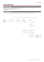
Page 11: ...Commissioning Preliminary settings At switch on the device displays two preliminary setting menus MID SETTINGS for EM530 MID models only QUICK SETUP MID SETTINGS menu This procedure only available in...

Page 12: ...s switched on for the first time Note the available parameters depend on the model In the QUICK SETUP starting page Select To Go run the QUICK SETUP procedure no skip the procedure and no longer displ...

Page 13: ...arh TOT kvar Imported reactive energy TOTAL System reactive power 8 kvarh TOT kvar Exported reactive energy TOTAL System reactive power 9 kVAh TOT kW kVA Apparent energy TOTAL System active power Syst...

Page 14: ...V L2 3 V L3 1 V Phase 1 phase 2 voltage Phase 2 phase 3 voltage Phase 3 phase 1 voltage 25 L1 A L2 A L3 A Phase 1 current Phase 2 current Phase 3 current 26 L1 kW L2 kW L3 kW Phase 1 active power Phas...

Page 15: ...VA kW SEt 1 Activation threshold 15000 to 15000 0 00 Set 2 Deactivation threshold 15000 to 15000 0 00 dELAY Activation delay 0 to 3600 s 0 dISPLAY LiGHt Timer for backlight switch off On always on 1 m...

Page 16: ...rm deactivation set point 25 ALArM dELAY Alarm activation delay 26 display LIGHt Backlight timer 27 display SC SAVEr Screensaver type 28 display home Home page 29 display PAGES Page filter enabling 30...

Page 17: ...partial meters Digital input status Action Open No action Closed After 3 seconds reset partial meters Digital output version O1 The digital output can perform two functions Function Description Param...

Page 18: ...OR logic phase phase voltage OR logic current OR logic Note if you select a current or a voltage the analyzer simultaneously monitors all the phases available in the set measurement system and trigger...

Page 19: ...gy meter Backlight EM530 and EM540 are equipped with a backlight system You can set whether the backlight shall always be ON or whether it should automatically switch off after a given interval has el...

Page 20: ...the factory settings Restoring the settings using the RESET menu From the RESET menu you can restore all the factory settings At start up the QUICK SET UP menu shall be available again Notes meters a...

Page 21: ...own at first power on EM530 MID models enter the reset menu and confirm MID res Note in MID models the reset can only be performed if the energy meter has not exceeded 1 kWh In case of wrong settings...

Page 22: ...ng error Virtual correction from UCS software or UCS Mobile The virtual correction function allows to calculate the wiring error solution and to modify the association of the physical connections with...

Page 23: ...ution An alarm is triggered but the measurement has not exceeded the threshold value The value with which the alarm variable is calculated is in error Check the set current transformer parameters The...

Page 24: ...brasives or solvents Responsibility for disposal Dispose of the unit by separately collecting its materials and bringing them to the facilities specified by government authorities or by local public b...

Page 25: ...EM530 EM540 Analizzatore di energia per sistemi trifase e bifase MANUALE D USO...

Page 26: ...0 Utilizzo del menu IMPOSTAZIONI 10 Utilizzo del menu INFO 10 Utilizzo del menu RESET 10 Messa in servizio 11 Impostazioni preliminari 11 Menu IMPOSTAZIONI MID 11 Menu QUICK SETUP 12 Descrizione dei m...

Page 27: ...u RESET 20 Ripristino del menu MID usando il menu RESET 21 Funzione WIRING CHECK 22 Introduzione 22 Display check 22 Controllo da software UCS 22 Correzione virtuale da software UCS o UCS Mobile 22 Ge...

Page 28: ...ebbe essere consultato per tutte le situazioni legate alla configurazione all uso e alla manutenzione Per questa ragione dovrebbe essere sempre accessibile agli operatori AVVERTENZA nessuno autorizzat...

Page 29: ...del modello di un uscita statica impulso o allarme una porta di comunicazione Modbus RTU o una porta di comunicazione M Bus Descrizione EM530 Parte anteriore Area Descrizione A Ingressi tensione B Di...

Page 30: ...ne diretta sino a 65 A Uscita digitale x EM540DINAV23XS1X Connessione diretta sino a 65 A RS485 Modbus RTU x EM540DINAV23XM1X Connessione diretta sino a 65 A M Bus x EM540DINAV23XO1PFA EM540DINAV23XO1...

Page 31: ...M530 o EM540 tramite RS485 protocollo RTU solo versione desktop UCS consente di configurare l unit online o offline visualizzare lo stato del sistema a scopi di verifica diagnostica e di setup Panoram...

Page 32: ...tati RESET pagine che consentono di resettare i contatori parziali e il calcolo dmd o di ripristinare le impostazioni di fabbrica Display menu SETTINGS Parte Descrizione A Titolo sottomenu vedere Menu...

Page 33: ...il controllo funziona correttamente se il sistema selezionato 3Pn e per ciascuna fase la potenza positiva importata PF 0 7 L o PF 0 96 C Stato comunicazione seriale ricezione trasmissione L associazio...

Page 34: ...l menu Principale Utilizzo del menu IMPOSTAZIONI Funzionamento Pulsante Scorrimento menu modifica parametri Ingresso nel sottomenu per modificare e confermare l operazione Utilizzo del menu INFO Funzi...

Page 35: ...Impostazioni preliminari All accensione il dispositivo visualizza due menu di impostazioni preliminari IMPOSTAZIONI MID per EM530 solo modelli MID QUICK SETUP Menu IMPOSTAZIONI MID Questa procedura di...

Page 36: ...acceso la prima volta Nota i parametri disponibili dipendono dal modello Nella pagina di avvio QUICK SETUP Selezionare Per Go eseguire la procedura QUICK SETUP no saltare la procedura e non visualizza...

Page 37: ...ystem 7 kvarh TOT kvar Energia reattiva importata TOTALE Potenza reattiva sistema 8 kvarh TOT kvar Energia reattiva esportata TOTALE Potenza reattiva sistema 9 kVAh TOT kW kVA Energia apparente TOTALE...

Page 38: ...V L3 1 V Tensione fase 1 fase 2 Tensione fase 2 fase 3 Tensione fase 3 fase 1 25 L1 A L2 A L3 A Corrente fase 1 Corrente fase 2 Corrente fase 3 26 L1 kW L2 kW L3 kW Potenza attiva fase 1 Potenza atti...

Page 39: ...V L L PF Kvar kVA kW SEt 1 Soglia di attivazione da 15000 a 15000 0 00 Set 2 Soglia di disattivazione da 15000 a 15000 0 00 dELAY Ritardo attivazione da 0 a 3600 s 0 dISPLAY LiGHt Timer per spegnimen...

Page 40: ...tivazione allarme 25 ALArM dELAY Ritardo attivazione allarme 26 display LIGHt Timer retroilluminazione 27 display SC SAVEr Tipo di screensaver 28 display home Home page 29 display PAGES Abilitazione f...

Page 41: ...ettare i contatori parziali Stato ingresso digi tale Azione Aperto Nessuna azione Chiuso Dopo 3 secondi reset dei contatori parziali Uscita digitale versione O1 L uscita digitale pu effettuare due fun...

Page 42: ...ca OR tensione fase fase logica OR corrente logica OR Nota se si seleziona una corrente o una tensione l analizzatore monitora contemporaneamente tutte le fasi disponibili nel sistema di misura impost...

Page 43: ...energia attiva Retroilluminazione EM530 e EM540 sono muniti di un sistema di retroilluminazione possibile impostare se la retroilluminazione deve sempre essere ON o se deve spegnersi automaticamente...

Page 44: ...fabbrica Ripristino delle impostazioni usando il menu RESET Dal menu RESET possibile ripristinare tutte le impostazioni di fabbrica All avvio il menu QUICK SET UP sar di nuovo disponibile Note i conta...

Page 45: ...e sui modelli EM530 MID entrare nel menu reset e confermare MID res Nota nei modelli MID il reset pu essere effettuato solo se il contatore di energia non ha superato 1 kWh Nel caso di impostazioni er...

Page 46: ...io Correzione virtuale da software UCS o UCS Mobile La funzione di correzione virtuale consente di calcolare la soluzione dell errore di cablaggio e di modificare l associazione delle connessioni fisi...

Page 47: ...vato un allarme ma la misura non ha superato il valore soglia Il valore con cui viene calcolata la variabile di allarme in errore Verificare i parametri correnti del trasformatore di corrente L allarm...

Page 48: ...mido Non utilizzare mai abrasivi o solventi Responsabilit dello smaltimento Smaltire l unit separatamente raccogliendo i suoi materiali e portandoli agli impianti specificati dalle autorit governative...

Page 49: ...EM530 EM540 Energieanalysator f r Dreiphasen und Zweiphasensysteme BETRIEBSANLEITUNG...

Page 50: ...ten mit EM530 EM540 10 Arbeiten mit den Messseiten 10 Arbeiten mit dem SETTINGS Men 10 Arbeiten mit dem INFO Men 10 Arbeiten mit dem RESET Men 10 Inbetriebnahme 11 Voreinstellungen 11 MID SETTINGS Men...

Page 51: ...stellungen ber das RESET Men 20 Wiederherstellen des MID Men s ber das RESET Men 21 WIRING CHECK Funktion 22 Einleitung 22 Anzeigepr fung 22 berpr fung von der UCS Software aus 22 Virtuelle Korrektur...

Page 52: ...sdauer Sie sollte in allen Situationen betreffend Konfiguration Gebrauch und Instandhaltung zu Rate gezogen werden Deshalb sollte sie dem Benutzer jederzeit zug nglich sein HINWEIS Niemand ist autoris...

Page 53: ...ach Modell mit einem statischen Ausgang Impuls oder Alarm einem Modbus RTU Kommunikationsport oder einem M Bus Kommunikationsport ausgestattet werden Beschreibung EM530 Vorderseite Bereich Beschreibun...

Page 54: ...nschluss bis zu 65 A Digitalausgang x EM540DINAV23XS1X Direktanschluss bis zu 65 A RS485 Modbus RTU x EM540DINAV23XM1X Direktanschluss bis zu 65 A M Bus x EM540DINAV23XO1PFA EM540DINAV23XO1PFB EM540DI...

Page 55: ...ar Die Verbindung zum EM530 oder EM540 kann ber RS485 RTU Protokoll nur Desktop Version erfolgen UCS erlaubt die Einheit einzurichten online oder offline den Systemzustand zu Diagnose und Setup Verifi...

Page 56: ...RESET Seiten die es erm glichen die Partialz hler und die dmd Berechnung zur ckzusetzen oder die Werkseinstellungen wiederherzustellen Anzeige des Men s SETTINGS Teil Beschreibung A Titel des Unterme...

Page 57: ...Steuerung arbeitet korrekt wenn das gew hlte System 3Pn ist und f r jede Phase gilt die Leistung ist positiv importiert PF 0 7 L oder PF 0 96 C Zustand der seriellen Kommunikation Empfang bertragung D...

Page 58: ...n aufrufen Arbeiten mit dem SETTINGS Men Operation Taste Durch das Men scrollen die Parameter bearbeiten Das Untermen zur Bearbeitung aufrufen und den Vorgang best tigen Arbeiten mit dem INFO Men Oper...

Page 59: ...ahme Voreinstellungen Beim Einschalten zeigt das Ger t zwei Voreinstellungsmen s an MID SETTINGS f r EM530 nur f r MID Modelle QUICK SETUP MID SETTINGS Men Dieses Verfahren das nur bei MID Modellen ve...

Page 60: ...lich Hinweis Die verf gbaren Parameter h ngen vom Modell ab Auf der QUICK SETUP Startseite W hlen Sie Um Gehen den QUICK SETUP Vorgang auszuf hren no den Vorgang zu berspringen und das QUICK SETUP Men...

Page 61: ...eistung Nachfrage System Wirkleistung 7 kvarh TOT kvar Bezogene Blindenergie GESAMT System Blindleistung 8 kvarh TOT kvar Abgegebene Blindenergie GESAMT System Blindleistung 9 kVAh TOT kW kVA Scheinen...

Page 62: ...ase 1 Spannung Phase 2 Spannung Phase 3 24 L1 2 V L2 3 V L3 1 V Spannung Phase 1 Phase 2 Spannung Phase 2 Phase 3 Spannung Phase 3 Phase 1 25 L1 A L2 A L3 A Strom Phase 1 Strom Phase 2 Strom Phase 3 2...

Page 63: ...le 15000 bis 15000 0 00 Set 2 R cksetzschwelle 15000 bis 15000 0 00 dELAY Aktivierung Verz gerung 0 bis 3600 s 0 dISPLAY LiGHt Timer f r die Abschaltung der Hintergrundbeleuchtung On durchgehend an 1...

Page 64: ...display LIGHt Timer f r Hintergundbeleuchtung 27 display SC SAVEr Typ des Bildschirmschoners 28 display home Homepage 29 display PAGES Seitenfilter aktivieren 30 display WirinG Verkabelungspr fung akt...

Page 65: ...nutzt Digitaleingangsstatus Aktion Offen Keine Aktion Geschlossen Nach 3 Sekunden Partial z hler zur cksetzen Digitalausgang O1 Version Der Digitalausgang kann zwei Funktionen ausf hren Funktion Besch...

Page 66: ...annung OR Logik Strom OR Logik Hinweis Wenn Sie einen Strom oder eine Spannung w hlen berwacht der Analysator gleichzeitig alle im eingestellten Messsystem verf gbaren Phasen und l st den Alarm aus we...

Page 67: ...grundbeleuchtung EM530 und EM540 sind mit einem Hintergrundbeleuchtungssystem ausgestattet Sie k nnen einstellen ob die Hintergrundbeleuchtung immer eingeschaltet sein soll oder ob sie nach Ablauf ein...

Page 68: ...en Wiederherstellen der Einstellungen ber das RESET Men ber das RESET Men k nnen Sie alle Werkseinstellungen wiederherstellen Bei der Inbetriebnahme ist das QUICK SET UP Men wieder verf gbar Hinweise...

Page 69: ...ID Modellen gezeigt wird ffnen Sie das RESET Men und best tigen MID res Hinweis Bei MID Modellen kann der Reset nur durchgef hrt werden wenn der Energiez hler 1 kWh nicht berschritten hat Im Fall von...

Page 70: ...kabelungsfehlers durchf hren Virtuelle Korrektur durch UCS Software oder UCS Mobile Die virtuelle Korrekturfunktion erm glicht die Berechnung der Verkabelungsfehlerl sung und die nderung der Zuordnung...

Page 71: ...Alarm wird ausgel st aber die Messung hat die Schwelle nicht berschritten Der Wert mit dem die Alarmvariable berechnet wird ist fehlerhaft berpr fen Sie die eingestellten Stromwandlerparameter Der Ala...

Page 72: ...ls Scheuer oder L sungsmittel Verantwortlichkeit f r Entsorgung Entsorgen Sie die Einheit indem Sie ihre Materialien getrennt sammeln und zu den von den Beh rden oder lokalen ffentlichenEinrichtungena...

Page 73: ...EM530 EM540 Analyseur d nergie pour syst mes bi et triphas s MANUEL D EMPLOI...

Page 74: ...r avec la page de mesures 10 Travailler avec le menu SETTINGS 10 Travailler avec le menu INFO 10 Travailler avec le menu RESET 10 Mise en service 11 R glages pr liminaires 11 Menu MID SETTINGS 11 Menu...

Page 75: ...20 Restauration du menu MID en utilisant le menu RESET 21 Fonction WIRING CHECK 22 Introduction 22 V rification d affichage 22 V rification partir du logiciel UCS 22 Correction virtuelle partir du lo...

Page 76: ...e de vie Il doit tre consult pour toutes les situations li es la configuration et l entretien Pour cette raison il devra toujours tre accessible aux op rateurs AVERTISSEMENT personne n est autoris ouv...

Page 77: ...p selon le mod le d une sortie statique impulsion ou alarme d un port de communication Modbus RTU ou d un port de communication M Bus Description EM530 De face Zone Description A Entr es de tension B...

Page 78: ...um rique x EM540DINAV23XS1X Connexion directe jusqu 65 A RTU Modbus RS485 x EM540DINAV23XM1X Connexion directe jusqu 65 A M Bus x EM540DINAV23XO1PFA EM540DINAV23XO1PFB EM540DINAV23XO1PFC Connexion dir...

Page 79: ...u EM530 ou au EM540 via RS485 protocole RTU version bureautique uniquement UCS permet de configurer l unit en ligne ou hors ligne afficher l tat du syst me des fins de diagnostic et de v rification de...

Page 80: ...permettant de remettre z ro les compteurs partiels et le calcul dmd ou de restaurer les r glages d usine Affichage du menu SETTINGS Pi ce Description A Titre du sous menu voir Menu param tres B Param...

Page 81: ...la commande fonctionne correctement si le syst me s lectionn est 3Pn et si pour chaque phase l alimentation est positive import e PF 0 7 L ou PF 0 96 C tat de communication en s rie r ception transmis...

Page 82: ...u principal Travailler avec le menu SETTINGS Fonctionnement Bouton Faire d filer le menu et diter les param tres Entrer dans le sous menu pour diter et confirmer l op ration Travailler avec le menu IN...

Page 83: ...es Lors de la mise sous tension l appareil affiche deux menus de r glage pr liminaires MID SETTINGS pour les mod les EM530 et MID uniquement CONFIGURATION RAPIDE Menu MID SETTINGS Cette proc dure disp...

Page 84: ...sion de l appareil Remarque les param tres disponibles d pendent du mod le Dans la page de d marrage QUICK SETUP S lectionner Aller ex cuter la proc dure QUICK SETUP non passer la proc dure et ne plus...

Page 85: ...t me Demande Puissance active syst me 7 kvarh TOT kvar nergie r active import e TOTALE Puissance r active syst me 8 kvarh TOT kvar nergie r active export e TOTALE Puissance r active syst me 9 kVAh TOT...

Page 86: ...ion de phase 2 Tension de phase 3 24 L1 2 V L2 3 V L3 1 V Tension phase 1 phase 2 Tension phase 2 phase 3 Tension phase 3 phase 1 25 L1 A L2 A L3 A Courant phase 1 Courant phase 2 Courant phase 3 26 L...

Page 87: ...r kVA kW SEt 1 Seuil d activation 15000 15000 0 00 Set 2 Seuil de d sactivation 15000 15000 0 00 dELAY Retard activation 0 3600 0 dISPLAY LiGHt Minuteur pour l extinction du r tro clairage On toujours...

Page 88: ...signe de d sactivation alarme 25 ALArM dELAY Retard activation alarme 26 display LIGHt Minuteur r tro clair 27 display SC SAVEr Type conomiseur d cran 28 display home Page d accueil 29 display PAGES A...

Page 89: ...t entr e logique Action Ouvert Sans action Ferm Apr s 3 secondes remettre z ro les compteurs partiels Sortie Num rique version O1 La sortie num rique peut ex cuter les deux fonctions suivantes Fonctio...

Page 90: ...e logique OU tension phase phase logique OU courant logique OU Remarque si vous s lectionnez un courant ou une tension l analyseur surveille simultan ment toutes les phases disponibles dans le syst me...

Page 91: ...ifi e et affiche le compteur d nergie active R tro clair EM530 et EM540 sont quip s d un syst me de r tro clairage Vous pouvez d finir si le r tro clairage doit toujours tre allum ou s il doit s teind...

Page 92: ...r glages en utilisant le menu RESET Dans le menu RESET vous pouvez restaurer tous les r glages d usine Au d marrage le menu QUICK SET UP devrait tre de nouveau disponible Remarques les compteurs ne so...

Page 93: ...les mod les EM530 MID entrez dans le menu de r initialisation et confirmez MID res Remarque dans les mod les MID la r initialisation ne peut tre effectu e que si le compteur d nergie n a pas d pass 1...

Page 94: ...r corriger l erreur de c blage Correction virtuelle partir du logiciel UCS ou de l application Mobile UCS La fonction de correction virtuelle permet de calculer la solution l erreur de c blage et de m...

Page 95: ...ench e mais la mesure n a pas d pass la valeur seuil La valeur avec laquelle la variable d alarme est calcul e est erron e V rifier les param tres du transformateur de courant r gl s L alarme n est pa...

Page 96: ...ou de solvants Responsabilit de l limination liminer l appareil en collectant s par ment ses mat riaux et en les apportant des organismes sp cifi s par les autorit s gouvernementales ou par les organi...

Page 97: ...EM530 EM540 Analizador de energ a para sistemas trif sicos y bif sicos MANUAL DE USUARIO...

Page 98: ...Operaciones con las p ginas de medici n 10 Operaciones con el men SETTINGS 10 Operaciones con el men INFO 10 Operaciones con el men RESET 10 Puesta en servicio 11 Configuraci n preliminar 11 Men MID S...

Page 99: ...RESET 20 Restablecimiento del men MID usando el men RESET 21 Funci n WIRING CHECK 22 Introducci n 22 Comprobaci n de la visualizaci n 22 Comprobaci n desde el software UCS 22 Correcci n virtual desde...

Page 100: ...de toda su vida til Debe consultarse para todo lo que tenga que ver con su configuraci n uso y mantenimiento Por este motivo los operadores deben disponer de acceso a l en todo momento ADVERTENCIA na...

Page 101: ...unidad puede estar equipada seg n el modelo con una salida est tica pulso o alarma un puerto de comunicaci n Modbus RTU o un puerto de comunicaci n M Bus Descripci n EM530 parte frontal rea Descripci...

Page 102: ...Lus EM540DINAV23XO1X Conexi n directa de hasta 65 A Salida digital x EM540DINAV23XS1X Conexi n directa de hasta 65 A Puerto RS485 Modbus RTU x EM540DINAV23XM1X Conexi n directa de hasta 65 A M Bus x E...

Page 103: ...otocolo RTU solamente versi n para escritorio El UCS permite configurar la unidad con o sin conexi n ver el estado del sistema con fines de diagn stico y verificaci n de la configuraci n Descripci n g...

Page 104: ...nas que permiten reiniciar los contadores parciales y el c lculo dmd o restablecer la configuraci n de f brica Visualizaci n del men SETTINGS Parte Descripci n A T tulo del submen ver Men SETTINGS B P...

Page 105: ...ontrol funciona correctamente si el sistema seleccionado es 3Pn y para cada fase la potencia es positiva importada PF 0 7 L o PF 0 96 C Estado de la comunicaci n serial recepci n transmisi n La asocia...

Page 106: ...r las p ginas Acceder al men principal Operaciones con el men SETTINGS Operaci n Bot n Recorrer el men editar los par metros Acceder al submen para editar y confirmar la operaci n Operaciones con el m...

Page 107: ...liminar Cuando se enciende el dispositivo muestra dos men s de configuraci n preliminares MID SETTINGS para el EM530 solamente para los modelos MID CONFIGURACI N R PIDA Men MID SETTINGS Este procedimi...

Page 108: ...r primera vez Nota los par metros disponibles dependen del modelo En la p gina de inicio QUICK SETUP Seleccione Para Go ejecutar el procedimiento QUICK SETUP no obviar el procedimiento y evitar que se...

Page 109: ...kvarh TOT kvar Energ a reactiva consumida TOTAL Potencia reactiva del sistema 8 kvarh TOT kvar Energ a reactiva generada TOTAL Potencia reactiva del sistema 9 kVAh TOT kW kVA Energ a aparente TOTAL P...

Page 110: ...e fase 3 24 L1 2 V L2 3 V L3 1 V Tensi n fase 1 fase 2 Tensi n fase 2 fase 3 Tensi n fase 3 fase 1 25 L1 A L2 A L3 A Intensidad fase 1 Intensidad fase 2 Intensidad fase 3 26 L1 kW L2 kW L3 kW Potencia...

Page 111: ...00 0 00 Set 2 Umbral de desactivaci n 15 000 a 15 000 0 00 dELAY Retardo activaci n 0 a 3600 s 0 dISPLAY LiGHt Temporizador del apagado de la retroiluminaci n On siempre encendido 1 min 2 min 5 min 10...

Page 112: ...rma 25 ALArM dELAY Retardo activaci n alarma 26 display LIGHt Temporizador de retroiluminaci n 27 display SC SAVEr Tipo de protector de pantalla 28 display home P gina de inicio 29 display PAGES Habil...

Page 113: ...edidores parciales Estado de entrada digital Acci n Abierto Sin acci n Cerrado Despu s de 3 segundos se rei nician los medidores parciales Salida digital versi n O1 La salida digital puede llevar a ca...

Page 114: ...ca OR tensi n fase fase l gica OR intensidad l gica OR Nota si selecciona una intensidad o una tensi n el analizador controlar simult neamente todas las fases disponibles en el sistema de medici n con...

Page 115: ...estra el medidor de energ a activa Retroiluminaci n El EM530 y el EM540 cuentan con un sistema de retroiluminaci n Puede configurar la retroiluminaci n de modo que est siempre encendida o para que se...

Page 116: ...Restablecimiento de la configuraci n con el men RESET Desde el men RESET puede restablecer todos los ajustes de f brica Cuando el sistema arranque el men QUICK SET UP volver a estar disponible Notas l...

Page 117: ...os MID EM530 entre en el men de restablecimiento y confirme MID res Nota en los modelos MID el reinicio nicamente se puede llevar a cabo si el medidor de energ a no ha superado 1 kWh En caso de que lo...

Page 118: ...virtual desde el software UCS o UCS Mobile La funci n de correcci n virtual permite calcular la soluci n para el error de cableado y modificar la asociaci n de las conexiones f sicas con las referenci...

Page 119: ...medici n no ha superado el valor del umbral El valor con el que se ha calculado la variable de la alarma es incorrecto Compruebe los par metros del transformador de intensidad configurado La alarma no...

Page 120: ...e nunca abrasivos ni disolventes Responsabilidad de la eliminaci n Deseche la unidad separando sus materiales y llev ndolos a los centros se alados por las autoridades gubernamentales o los organismos...

Page 121: ...EM530 EM540 Energianalysator til to og trefasede systemer BRUGERMANUAL...

Page 122: ...rbejde med afl sningssider 10 Arbejde med menuen SETTINGS 10 Arbejde i menuen INFO 10 Arbejde i menuen RESET 10 Ibrugtagning 11 Forel bige indstillinger 11 Menuen MID SETTINGS 11 Menuen QUICK SETUP 12...

Page 123: ...af menuen RESET 20 Gendannelse af menuen MID ved brug af menuen RESET 21 Funktionen WIRING CHECK 22 Introduktion 22 Tjek af display 22 Tjek fra UCS software 22 Virtuel rettelse fra UCS software eller...

Page 124: ...n skal altid konsulteres i alle situationer som drejer sig om konfiguration brug og vedligeholdelse Af denne grund skal den altid v re tilg ngelig for brugerne MEDDELELSE Ingen er autoriseret til bnin...

Page 125: ...den i henhold til modellen udstyres med en statisk udgang impuls eller alarm en Modbus RTU kommunikationsport eller en M Bus kommunikationsport Beskrivelse EM530 Forside Omr de Beskrivelse A Sp ndings...

Page 126: ...ekte tilslutning op til 65 A Digital udgang x EM540DINAV23XS1X Direkte tilslutning op til 65 A RS485 Modbus RTU x EM540DINAV23XM1X Direkte tilslutning op til 65 A M Bus x EM540DINAV23XO1PFA EM540DINAV...

Page 127: ...r Den kan tilsluttes EM530 eller EM540 via RS485 RTU protokol kun desktop version Med UCS kan du ops tte enheden online eller offline f vist systemstatus for fejlfinding og ops tningsverifikation Over...

Page 128: ...hvor du kan nulstille delt llerne og dmd beregningen eller hvor du kan gendanne fabriksindstillingerne Visning af menuen SETTINGS Del Beskrivelse A Undermenunavn se menuen SETTINGS INDSTILLINGER B Par...

Page 129: ...en ledningsfejl Kontrollen er korrekt hvis det valgte system er 3Pn og f lgende g lder for hver fase Effekten er positiv importeret PF 0 7 L eller PF 0 96 C Seriel kommunikationstilstand modtagelse tr...

Page 130: ...e G til hovedmenuen Arbejde med menuen SETTINGS Handling Knap Rul ned gennem menuen og rediger parametrene G til undermenuen for at redigere og bekr fte handlingen Arbejde i menuen INFO Handling Knap...

Page 131: ...orel bige indstillinger Ved t nding viser enheden to forel bige indstillingsmenuer MID SETTINGS kun for EM530 MID modeller QUICK SETUP Menuen MID SETTINGS Denne procedure som kun er tilg ngelig for MI...

Page 132: ...entet t ndes for f rste gang Bem rk De tilg ngelige parametre afh nger af modellen P startsiden QUICK SETUP V lg For at G k re proceduren QUICK SETUP Nej springe proceduren over og ikke l ngere vise m...

Page 133: ...d system om aktiv effekt 7 kvarh TOT kvar Importeret reaktiv energi TOTAL Reaktiv systemeffekt 8 kvarh TOT kvar Eksporteret reaktiv energi TOTAL Reaktiv systemeffekt 9 kVAh TOT kW kVA Tilsyneladende e...

Page 134: ...nding Fase 2 sp nding Fase 3 sp nding 24 L1 2 V L2 3 V L3 1 V Fase 1 fase 2 sp nding Fase 2 fase 3 sp nding Fase 3 fase 1 sp nding 25 L1 A L2 A L3 A Fase 1 str m Fase 2 str m Fase 3 str m 26 L1 kW L2...

Page 135: ...W SEt 1 Aktiveringst rskel 15000 til 15000 0 00 Set 2 Deaktiveringst rskel 15000 til 15000 0 00 dELAY Aktiveringsforsinkelse 0 3600 sek 0 dISPLAY LiGHt Timer til slukning af baggrundslys On altid t nd...

Page 136: ...nsev rdi for deaktivering af alarm 25 ALArM dELAY Alarmaktiveringsforsinkelse 26 display LIGHt Timer til baggrundslys 27 display SC SAVEr Pausesk rmtype 28 display home Startside 29 display PAGES Akti...

Page 137: ...ere Status p digital indgang Handling bent Ingen handling Lukket Nulstil delm lere efter 3 sekunder Digital udgang version O1 Den digitale udgang kan udf re to funktioner Funktion Beskrivelse Parametr...

Page 138: ...sp nding OR logik fase fase sp nding OR logik str m OR logik Bem rk Hvis du v lger en str m eller sp nding overv ger analysatoren samtidigt alle de faser der er tilg ngelige i det opsatte m lesystem...

Page 139: ...n aktive energim ler Baggrundsbelyst EM530 og EM540 er udstyret med et baggrundsbelyst system Du kan indstille om baggrundsbelysningen altid skal v re t ndt ON eller om den skal slukke automatisk efte...

Page 140: ...illinger Gendannelse af indstillingerne ved brug af menuen RESET I menuen RESET Nulstil kan du gendanne alle fabriksindstillinger Ved opstart skal menuen QUICK SET UP v re tilg ngelig igen Bem rk M le...

Page 141: ...n f rste t nding for EM530 MID modeller skal du g til nulstillingsmenuen og bekr fte MID res Bem rk IMID modellerkannulstillingenkunudf res hvisenergim lerenikkeoverskrider1kWh Hvisdulaverenforkertind...

Page 142: ...ftware eller UCS Mobile Den virtuel rettelse g r det muligt at beregne en l sning for ledningsfejlen og tilpasse de fysiske forbindelser med afl sningsreferencerne Eksempel Hvis forbindelserne til ter...

Page 143: ...Mulig l sning En alarm er blevet udl st men m lev rdien overskrider ikke gr nsev rdien V rdien som alarmvariablen beregnes ud fra er fejlbeh ftet Tjek parametrene for indstillingen af str mtransformer...

Page 144: ...displayet Brug aldrig slibende midler eller opl sningsmidler Ansvar for bortskaffelse Enheden afleveres hos den kommunale indsamlingsordning som angivet af lovgivningen eller de lokale myndigheder En...

Page 145: ...EM530 EM540...

Page 146: ...EM540 5 5 5 6 UCS 7 8 8 8 SETTINGS 8 INFO 8 RESET 8 8 9 EM530 EM540 10 10 SETTINGS 10 INFO 10 RESET 10 11 11 MID SETTINGS 11 QUICK SETUP 12 13 13 SETTINGS 14 INFO 15 RESET 16 17 17 O1 17 Modbus RTU S1...

Page 147: ...3 EM530 EM540 CARLO GAVAZZI Controls SpA 19 LCD 19 19 19 19 19 20 RESET 20 RESET MID 21 WIRING CHECK 22 22 22 UCS 22 UCS UCS 22 22 22 Modbus RTU 22 23 23 23 23 23...

Page 148: ...GAVAZZI Controls SpA CARLO GAVAZZI CARLO GAVAZZI www productselection net MANUALS UK EM530_EM540_im_use pdf EM530 www productselection net MANUALS UK EM530_im_inst pdf EM540 www productselection net...

Page 149: ...5 EM530 EM540 CARLO GAVAZZI Controls SpA EM530 EM540 EM530 5 A 415 V L L EM540 65 A 415 V L L Modbus RTU M Bus EM530 A B C LED D E F MID G EM540 A B C LED D E F MID...

Page 150: ...RS485 Modbus RTU X EM530DINAV23XM1PFA EM530DINAV23XM1PFB EM530DINAV23XM1PFC CT 5A M Bus X MID cULus EM540DINAV23XO1X 65 A X EM540DINAV23XS1X 65 A RS485 Modbus RTU X EM540DINAV23XM1X 65 A M Bus X EM54...

Page 151: ...7 EM530 EM540 CARLO GAVAZZI Controls SpA PFC kWh kWh P L1 2 kW P L2 2 kW P L3 3 kW 1 kWh 2 2 3 x 1h 1 x1h 1 kWh kWh 0 kWh UCS UCS RS485 RTU EM530 EM540 UCS UCS...

Page 152: ...8 EM530 EM540 CARLO GAVAZZI Controls SpA EM530 EM540 SETTINGS INFO RESET dmd SETTINGS A SETTINGS B INFO A INFO B RESET A B RESET C A B L C C...

Page 153: ...9 EM530 EM540 CARLO GAVAZZI Controls SpA 3Pn PF 0 7 L PF 0 96 C UCS MENU INFO TERMINAL...

Page 154: ...10 EM530 EM540 EM530 EM540 CARLO GAVAZZI Controls SpA EM530 EM540 SETTINGS INFO RESET...

Page 155: ...11 EM530 EM540 CARLO GAVAZZI Controls SpA MID SETTINGS EM530 MID QUICK SETUP MID SETTINGS MID CT...

Page 156: ...12 EM530 EM540 CARLO GAVAZZI Controls SpA QUICK SETUP QUICK SETUP Go QUICK SETUP no QUICK SETUP LAtEr QUICK SETUP S1 M1 O1...

Page 157: ...PAR kW 4 kWh TOT kW PF 5 VLN VLL Hz 6 kWh TOT kW kW sys DMD 7 kvarh TOT kvar 8 kvarh TOT kvar 9 kVAh TOT kW kVA 10 kWh TOT h TOT kW kWh 11 kWh TOT h TOT kW kWh 12 kWh PAR h PAR kW kWh 13 kWh PAR h PA...

Page 158: ...1 V 1 2 2 3 3 1 25 L1 A L2 A L3 A 1 2 3 26 L1 kW L2 kW L3 kW 1 2 3 27 L1 kWh TOT L2 kWh TOT L3 kWh TOT 1 2 3 SETTINGS SYSTEM 3P N 3P 2P 3P N CT RAT CT 1 2000 1 MID AV5 MEASurE A B C A MID dMd int DMD...

Page 159: ...tuS No Nc ALARM EnAbLE no VAriAbLE kW A V L N V L L PF Kvar kVA kW SEt 1 15000 15000 0 00 Set 2 15000 15000 0 00 dELAY 0 3600 s 0 dISPLAY LiGHt On 1 min 2 min 5 min 10 min 15 min 30 min 60 min oFF On...

Page 160: ...tput Function O1 18 Output StAtuS O1 19 output duration O1 20 Output PuLSE O1 21 ALArM EnAbLe 22 ALArM VAriAbLE 23 ALArM SEt 1 24 ALArM SEt 2 25 ALArM dELAY 26 display LIGHt 27 display SC SAVEr 28 dis...

Page 161: ...0 EM530 EM540 CARLO GAVAZZI Controls SpA 1 2 Modbus M Bus 300h 0 1 3 O1 kWh kWh Modbus RTU S1 Modbus RTU Modbus Carlo Gavazzi UWP3 0 SCADA PLC BMS Modbus RTU M Bus M1 M Bus M Bus Carlo Gavazzi SIU MBM...

Page 162: ...CARLO GAVAZZI Controls SpA EM500 VARIABLE SET POINT 1 SET POINT 2 ACTIVATION DELAY Set point 1 Set point 2 Set 1 Delay Set 2 s ON Set 1 Set 2 Delay Set point 1 Set point 2 Set 1 Delay Set 2 s ON Set...

Page 163: ...15 min 10 13 07 15 min 10 28 07 10 13 07 10 28 07 LCD Home page MID EM530 EM540 1 60 SCREENSAVER 5 Home page MID Homepage UCS S1 O1 M1 UCS SETTINGS DISPLAY PAGES ALL 1 kWh TOT kW 2 kWh TOT kW 5 VLN V...

Page 164: ...20 EM530 EM540 CARLO GAVAZZI Controls SpA RESET RESET QUICK SET UP MID CT CT...

Page 165: ...21 EM530 EM540 CARLO GAVAZZI Controls SpA RESET MID CT EM530 MID MID MID res MID 1 kWh CT CT MID 1 kWh CT...

Page 166: ...ARLO GAVAZZI Controls SpA WIRING CHECK WIRING CHECK 1 3P N 2 3 45 15 0 7 0 96 WIRING V MISSING I MISSING PF OUT OF RANGE UCS UCS UCS UCS UCS 5 6 2 3 2 6 3 5 UCS MID UCS 1 2 Modbus RTU Modbus RTU UCS M...

Page 167: ...EM530 www productselection net MANUALS UK EM530_im_inst pdf EM530 http www productselection net Pdf UK EM530 pdf EM540 www productselection net MANUALS UK EM540_im_inst pdf EM540 http www productsele...

Page 168: ...24 EM530 EM540 CARLO GAVAZZI Controls SpA...

Page 169: ...530_EM540 User Manual 2021 09 Copyright 2020 CARLO GAVAZZI Controls SpA via Safforze 8 32100 Belluno BL Italy www gavazziautomation com info gavazzi automation com info 39 0437 355811 fax 39 0437 3558...

Reviews: