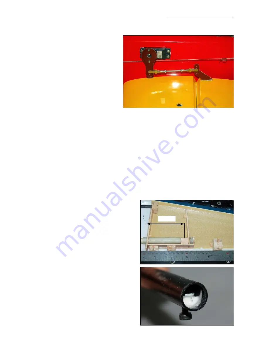
horns are in identical positions in rela-
tion to the hinge axis to give equal ele-
vator movements.
Put a layer of plastic parcel tape over
the area of
one
of the the milled slots,
wax it, and then cut through the tape
with a sharp knife to allow the horn to
be glued into the slots. This stops
excess glue getting on the surface of
the elevator. Adjust the slot in one ele-
vator so that the holes in the horn for
the clevise are exactly perpendicular
the elevator hinge axis, rough up the
gluing surface of the horn, and glue it
into the slot with 30min. epoxy and
microballoons.
When the glue has fully cured on the first horn, remove the tape, and make a horn alignment
template from thin plywood (see photo in wing section) and a 1.6mm drill or piece of wire, and
use it to install the horn in the other elevator. This ensures identical elevator throws.
Make up the extension leads for the 2 elevator servos, and centre both servos with your R/C.
Rough up the outer surface of two Ø 25mm metal servo output discs, and do the same on the
inner surface of two of the phenolic C-ARF servo arm extensions supplied. Glue the phenolic
arms to the discs with 30 minute epoxy and milled-fibre mixture, making sure that they are both
exactly at 90° to the bottom surface of the stabs. Remove the servos, and secure the phenolic
arms to the servo discs with 2 small bolts and nuts (M2 or equivalent) for each servo.
Make up the elevator linkages from the 60mm
long M3 threaded rods, with 2 clevises and 2 x
M3 nuts for each stab, as shown in the photos.
The clevise should be on the
inner
hole of the
servo extension arm, and on the elevator horn it
should be on the
3rd or 4th hole out
from the ele-
vator surface - to maximise the mechanical
advantage and reduce any chance of flutter.
With your transmitter throws set at maximum
(125%) this will still allow even the hi-rate/3D
throws mentioned at the end of the manual.
‘Loctite’ the quick-link and loc-nut on one end of
each linkage. Add a couple of short lengths of
silicone tube over all clevises to prevent them
opening accidentally in flight. Do
NOT
use ball-
links on the servo arms or the control-surface
horns, because they will twist the servo
arm/horn and cause flutter. This is a solid expe-
rience and you should consider it a
FACT
.
The stabs are secured to the carbon tube using
two M3 bolts, screwed thru’ the bottom surface
of the stabs, into T-nuts that you must glue
Composite-ARF Extra 300L
(2.12m/84”)
17
100mm
(above) Completed stab servo & linkage, also showing
the position of the M3 stab securing bolt, recessed
into the bottom of the stab. Note positions of clevises
on the horns for the maximum mechanical advantage.


