


ENG
“Power+” +0300050EN - rel. 2.3 - 08.06.2012
19
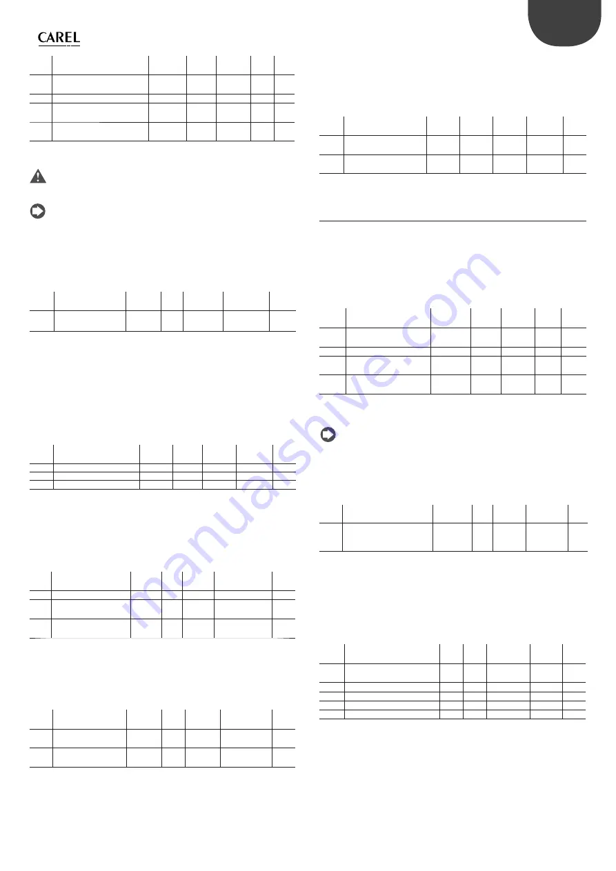
Mod.
add.
Description
Def
Min
Max
U.M. R/W
1
Motor base frequency
500
(50.0Hz)
250
(25.0Hz)
5000
(500.0Hz)
0.1Hz R/W
2
Motor base voltage
230/400
25
250/500
V
R/W
3
Motor rated current
Rated
current (*)
(*)
(*)
0.1A
R/W
4
Motor power factor (cos
) 100
(1.00)
0/50
(0.5)
100
(1.00)
0.01
R/W
Tab. 4.f
(*) Values are model dependent. See chapter 7 “PARAMETERS TABLE”.
Important:
the base frequency is used as reference for the parameter:
•
max frequency for starting current.
Note
: see the Appendix for the frequency to the revolution speed
conversion formulas, related to the number of motor poles.
Maximum motor current
The maximum motor current in the case of the compressor must be set
at 1000(=100.0%): as there is no necessity for quick accelerations, no peak
currents must be envisioned.
Mod.
add.
Description
Def
Min
Max
U.M.
R/W
5
Maximum output
current
1000
(100.0%)
0
2000
(200.0%)
0.1% Motor
rated current
R/W
Tab. 4.g
Motor electric data
The stator resistance is the resistance of the stator windings, measured
between phase and phase. In the mathematical model of the motor, Ld and
Lq are the inductance used in the reference system (d,q) rotating at rotor
speed.It is recommended to use the values indicated by CAREL depending
on the motors/compressors available. If the Autotuning is performed, these
parameters are set automatically at the end of the procedure on the basis of
the measurements detected.
Mod.
add.
Description
Def
Min
Max
U.M.
R/W
46
Stator resistance
0
0
38500
0.001ohm R/W
48
Stator inductance/Ld
0
0
6130
0.1mH
R/W
50
Lq inductance
0
0
6130
0.1mH
R/W
Tab. 4.h
Motor start-up
These parameters optimise the initial start-up phase of the motor and the
relative estimate of the position and the motor speed. It is recommended to
use the values indicated by CAREL depending on the motors/compressors
available. See paragraph 5.11 for the meaning of the parameters.
Mod.
add.
Description
Def
Min
Max
U.M.
R/W
51
Magnetizing time
100
0
30000
ms
R/W
57
Starting current
200
(20..0%)
0
1000
(100.0%)
0.1% Motor
rated curr.
R/W
58
Maximum frequency
for starting current
0
0
1000
(100.0%)
0.1% Motor
rated frequency
R/W
Tab. 4.i
Motor control in regenerative functioning mode
It is recommended to use the default values. Typically in the application with
compressors, the regenerative functioning mode never occurs. For particular
applications, consult CAREL.
Mod.
add.
Description
Def
Min
Max
U.M.
R/W
53
Regeneration current
limit
1000
(100.0%)
0
2000
(200.0%)
0.1% Motor
rated curr.
R/W
54
Overvoltage control
current limit
100
(10.0%)
0
2000
(200.0%)
0.1% Motor
rated curr.
R/W
Tab. 4.j
P
I parameters for speed regulation
In applications with slow acceleration and deceleration times, as with
compressors, it is recommended to use default values or the values indicated
by CAREL depending on the motors/compressors available. For particular
applications, consult CAREL.
Mod.
add.
Description
Def
Min
Max
U.M.
R/W
55
Speed loop: Kp
250
(25.0%)
1
(0.1%)
2000
(200.0%)
0.1%
R/W
56
Speed loop: Ti
500
(0.5s)
1
(0.001s)
1000
(1s)
1ms
R/W
Tab. 4.k
4.3 B - Asynchronous motor with vector control
Motor data plate
Frequency/voltage/rated current/power factor
The base frequency is the frequency at which the nominal voltage is applied.
If current peaks are necessary, the rated current of the motor must be lower
enough that the drive rated current. The power factor is the rated cos
of
the motor.
Mod.
add.
Description
Def
Min
Max
U.M.
R/W
1
Motor base frequency
500
(50.0Hz)
250
(25.0Hz)
5000
(500.0Hz)
0.1Hz
R/W
2
Motor base voltage
230/400
25
250/500
V
R/W
3
Motor rated current
Rated
current (*)
(*)
(*)
0.1A
R/W
4
Motor power factor
(cos
)
100
(1.00)
0/50
(0.5)
100
(1.00)
0.01
R/W
Tab. 4.l
(*) Values are model dependent. See chapter 7 “PARAMETERS TABLE”.
Note
: see the Appendix for the frequency to the revolution speed
conversion formulas, related to the number of motor poles.
Maximum motor current
If current peaks are necessary, set the “Maximum output current” a value
equivalent to the drive rated current.
Mod.
add.
Description
Def
Min
Max
U.M.
R/W
5
Maximum output current
1000
(100.0%)
0
2000
(200.0%)
0.1%
Motor rated
current
R/W
Tab. 4.m
Motor electric data
They are values that are diffi
cult to trace in the motors datasheets. It is
recommended to use the values indicated by CAREL depending on the
motors/compressors available. If the Autotuning is performed, these
parameters are set automatically at the end of the procedure on the basis of
the measurements detected.
Mod.
add.
Description
Def
Min
Max
U.M.
R/W
45
Motor magnetizing current
0
0
Motor rated
current
0.1A
R/W
46
Stator resistance
0
0
38500
mΩ
R/W
47
Rotor resistance
0
0
38500
mΩ
R/W
48
Stator inductance/Ld
0
0
6130
0.1mH
R/W
49
Leakage factor
0
0
250 (0.25)
0.01
R/W
Tab. 4.n
Summary of Contents for Power+
Page 2: ......
Page 4: ......
Page 6: ...ENG Power 0300050EN rel 2 3 08 06 2012 6 ...
Page 35: ......