


UI SmartSeatPro
II
User Guide. Iss1 06/22
12
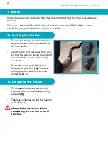
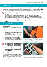
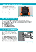
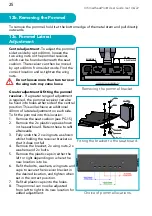
Locating the plunger pin.
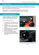
Parts of the footplate.
The footplate fits into the bracket
on the back of the leg rest.
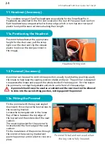
4. Height & Angle Adj. Flip-up Footplate UK Patent Approved
GB 2589439
A footplate is important for the user’s comfort, postural
stability and pressure distribution. The SmartSeatPro
II
footplate is also suitable for users with a longer lower
leg length. The footplate is fixed into a bracket on the
back of the leg rest. To insert and adjust the footplate
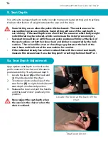
height:
1. Pull out the locating pin on the bracket and insert
the footplate.
2. Slide the footplate up or down to adjust to the
desired height.
3. Release the locking pin; the pin should ‘click’ into
position when the footplate is properly located.
•
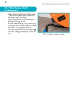
Note: The footplate stem has a ratchet and wheel
safety feature. This ensures that should the
footplate come into contact with the floor it will rise
up out of the way maintaining chair stability. The
wheel offers some protection to the flooring.
•
The ratchet feature is predominantly for safety;
we advise that the footplate height is reduced by
hand every time the leg rest is lowered.
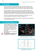
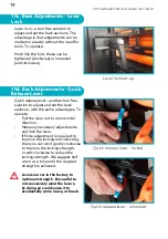
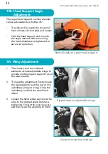
The footplate can be adjusted and set to a choice of 4 positions; 75°, 90°, 105° & 120°.
This equates to a 120° range of adjustment. In all angled positions the footplate can be
easily lifted up to 0
o
(vertical) to move it out of the way.
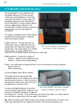
The SmartSeatPro
II
footplate angle can be adjusted
to correct positioning at the feet to neutral, or
accommodate fixed postures at the ankles. To adjust
the footplate angle:
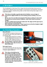
1. Ensure this operation is carried out by a competent
person, and that no weight is being applied to the
footplate.
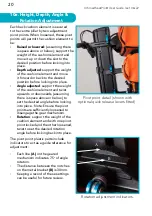
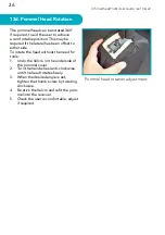
2. The position is set by the plunger pins as shown;
each indicator offers 1 of 4 different positions
and 0
o
is achieved when vertical. Pull out one of
the plungers and twist so that it is locked off (see
image).
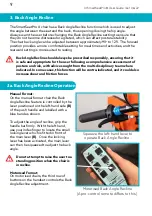
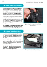
3. With one hand safely on the footplate, pull out the
second plunger pin so that the footplate can angle
to the desired setting.
4. When this is achieved, lock both plunger pins into
position, fully engaging with the corresponding
holes on each side.
5. The footplate will ‘flip-up’ to vertical 0
o
from any
position and return to its original setting.
•
Keep fingers away from the mechanism when
performing this task to avoid any potential finger
traps.
Unlocked
Locked


