background image


[email protected] 

docs.carbide3d.com


12/2/19  v1.0


Clear Offsets and Change to Machine Coordinates 

Clear Offsets 

1.


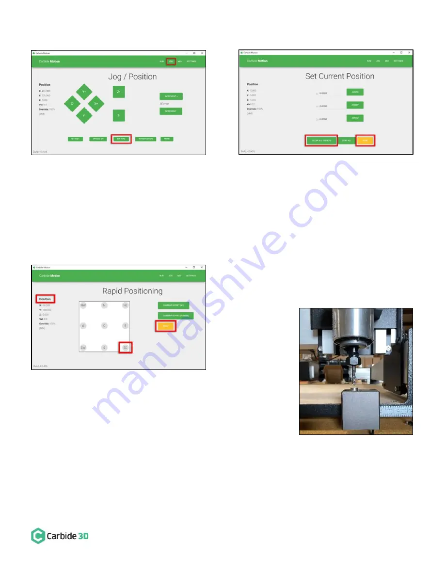
After homing completes, click Jog in the top menu bar. 

2.


Click the Set Zero button. See 

Figure 16

3.


On the Set Current Position screen, click the Clear All Offsets button. Then, click 

DONE

. See 

Figure 17

4.


Click the Position label. This will toggle the view to the machine coordinates. See 

Figure 18


5.


Click Rapid Position, then click the SE button to move the 
spindle to the front-right of the machine. Once in position, click 

DONE

. See 

Figure 18

6.


From the JOG screen, use the arrows on the screen (or the 
arrows on your keyboard) to jog the gantry so the spindle is 
directly above the BitSetter (as shown in 

Figure 19

).


Figure 16 

Figure 17 

Figure 18 

Figure 19 

Summary of Contents for BitSetter

Page 1: ...material once before running each project All subsequent tool changes will automatically be re zeroed BitSetter Kit Contents Item Description Qty Note A BitSetter 1 Tool Offset Probe B 3 Pin Cable 1 Connects Probe Adapter PCB to Carbide Motion Controller C Probe Adapter PCB 1 Accepts 2 Probe Inputs D Legacy Adapter Cable 1 Connects BitSetter to Carbide Motion Boards Prior to v2 4 E M4 x 4mm Grub S...

Page 2: ...plate about 4 5 inches 115mm from the right edge of the end plate See Figure 4 4 To make sure the spindle can touch the BitSetter without interference slowly move the gantry by hand so it is directly above the BitSetter Ensure the center of the spindle is in line with the center of the BitSetter See Figure 7 below 5 If necessary slide your BitSetter to the right or left along the front end plate t...

Page 3: ... yet See Figure 5 5 Slide the BitSetter over the lip of the front end plate about 4 5 inches 115mm from the right edge of the end plate 6 To make sure the spindle can touch the BitSetter without interference slowly move your gantry by hand so it is above the BitSetter Ensure the center of the spindle is in line with the center of the BitSetter See Figure 7 7 If necessary slide your BitSetter to th...

Page 4: ...se the included adhesive tie downs and zip ties to secure the cable to the machine We recommend one tie down immediately behind the BitSetter and another where the wire feeds out near the controller Routing Option 2 1 Using the cutout on the bottom of the BitSetter route the cable around the front left side of the machine 2 Use the included adhesive tie downs and zip ties to secure the cable to yo...

Page 5: ... included a variety of adapters to allow you to connect the BitSetter without needing to cut or solder any wires The instructions below apply to versions of the Carbide Motion boards shipped with Shapeoko 2 1 2 2 2 3 2 4d 2 4e To identify which version of the Carbide Motion board you own look in the bottom left corner of the PCB Figure 8 ...

Page 6: ... pin on the AVR PROGRAMMING label as shown in Figure 10 3 Once both wires are plugged in your board should look like Figure 11 4 Connect the Legacy Adapter Cable to the port labeled TO CARBIDE MOTION on the Probe Adapter PCB 5 Connect the BitSetter to the port labeled TOOL PROBE on the Probe Adapter PCB NOTE If you also have a Carbide 3D probe plug that into the port labeled TOUCH PROBE on the Pro...

Page 7: ...y into the port labeled RESERVED as shown in Figure 12 b If you have both the BitSetter and a Touch Probe use the Probe Adapter PCB as shown in Figure 13 NOTE If your 2 4d e board is missing the RESERVED label connect the Touch Probe using the adapter cable and follow the directions for connecting version 2 1 2 2 2 3 above 2 After your cable is routed to the Carbide Motion Controller re install th...

Page 8: ...rbide Motion v4 26 or higher is required to use the BitSetter If you have not already done so download the latest version of Carbide Motion now at carbide3d com carbidemotion Connect to Shapeoko 1 Open Carbide Motion 2 Power on the Shapeoko then click the Connect to Cutter button See Figure 14 3 After the software connects click the Initialize Machine button This will begin a homing cycle See Figu...

Page 9: ...utton Then click DONE See Figure 17 4 Click the Position label This will toggle the view to the machine coordinates See Figure 18 5 Click Rapid Position then click the SE button to move the spindle to the front right of the machine Once in position click DONE See Figure 18 6 From the JOG screen use the arrows on the screen or the arrows on your keyboard to jog the gantry so the spindle is directly...

Page 10: ...are using an HDZ 5 Select the BitSetter Probe checkbox This will expand the window and allow you to configure the permanent location of the BitSetter 6 With your spindle directly above the BitSetter click the Use Current X Y button to set the location This will permanently save the X Y location of your BitSetter NOTE If you physically change the BitSetter location you will need to re run this setu...

Page 11: ...tialization sequence is complete you can load and run a job by using the Load File feature Notes About Using Your BitSetter Ensure tools are long enough to reach the BitSetter trigger button The minimum length the tool must extend from the collet is 0 5 In order to instantiate a tool change and offset measurement your CAM program must post unique tool numbers with each new tool Carbide Create does...

Reviews: