background image

S T E P  4

S T E P   4   –   G a n t r y

22

docs.carbide3d.com

[email protected]

23

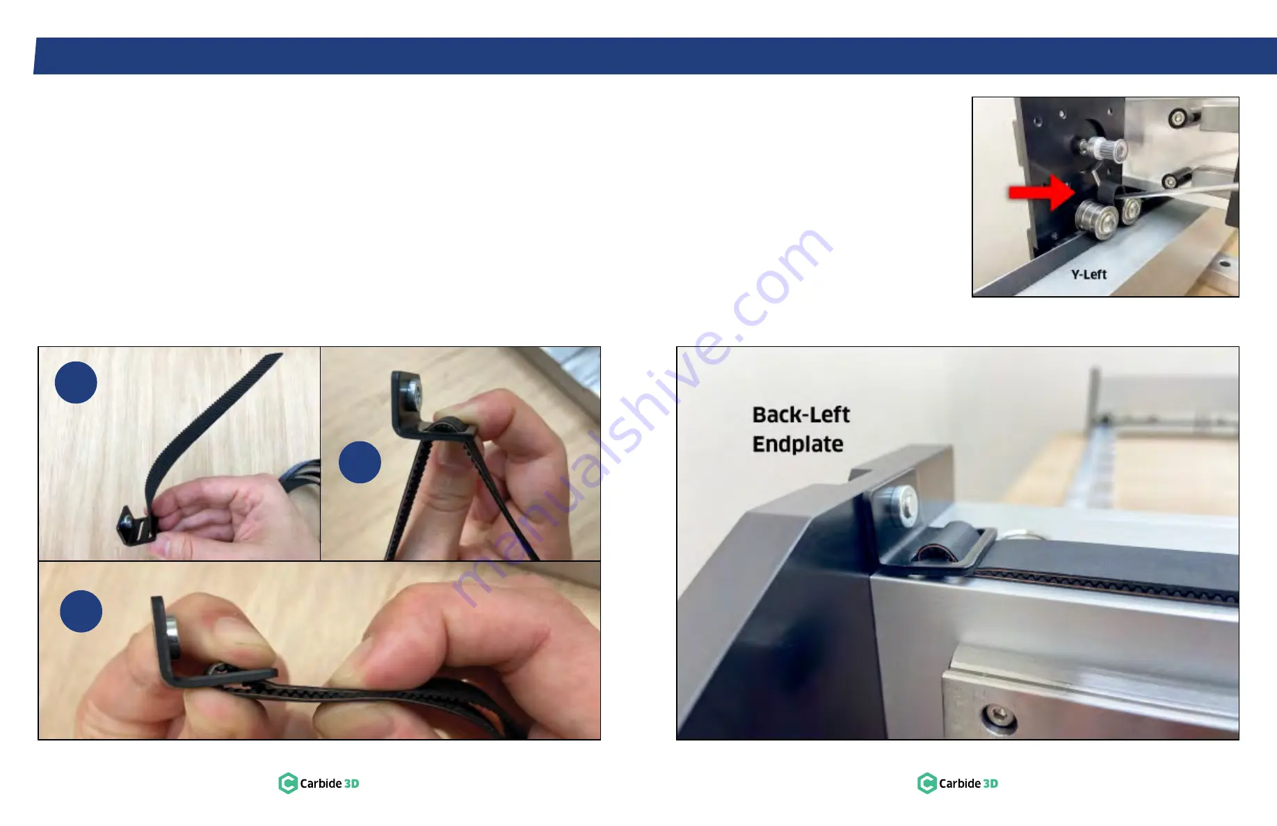
4.3   Attach Belt Clip to Belt

See 

Fig. 4-5

.

1.  Thread about 5 inches of belt through the 

outer slot of the clip, with teeth facing toward 

the integrated nut.

2.  Loop the belt down through the inner slot and 

pull the belt tight against the clip. 

3.  Bring the two sections of belt together. 

Interlock the teeth and extend the belt away 

from the integrated nut.

Figure 4-7

4.4   Install Y‑Axis Belts

1.  Use a 4mm hex key and one (1) M5×12mm 

SHCS to secure the clip to the back-left 

endplate. 

See 

Fig. 4-7

.

a.  Slotted end of the clip against the rail.
b.  Ensure belt teeth interlock where they 

meet at the clip.

c.  Ensure teeth face down as the belt 

extends along the rail.

d.  Fully tighten.

2.  Thread the belt, teeth down, under the two 

idlers onto the left gantry endplate.

3.  Use a small hex key to pull a loop of belt up 

between the two idlers. 

See 

Fig. 4-6

.

4.  Place the loop over the stepper motor pulley.

Figure 4-6

1

2

3

Figure 4-5

Summary of Contents for Shapeoko PRO

Page 1: ...Shapeoko PRO ASSEMBLY GUIDE...

Page 2: ...See the Glossary of Terms at the end of this guide for common CNC terms and definitions Have Questions Need Help We have a fully staffed support team waiting to help if you run into any trouble while...

Page 3: ...off the Shapeoko Pro immediately End Mill Safety Use care when handling end mills both to avoid being cut and to avoid damaging them Handling end mills with suitable gloves or using a cloth to avoid...

Page 4: ...tem Description Qty A Crossmember with Pre Installed Standoffs 4 B Y Axis LEFT Drag Chain Support Panel 1 C Y Axis RIGHT Drag Chain Support Panel 1 D Tool Kit 1 5 2 2 5 3 4 5mm Ball Nose Hex Keys 8 10...

Page 5: ...to the crossmembers See Figs 1 2 and 1 3 a Snug the screws then back out turn b Don t worry about squaring the baseframe yet Figure 1 3 1 3 Install Cable Tie Mounts 1 Use a 2mm hex key and four 4 M3 6...

Page 6: ...support carbide3d com 9 Box Components Step 2 Y Rails box contents see Fig 2 1 Item Description Qty I Y Axis LEFT Extrusion Rail Y Left Rail 1 J Y Axis RIGHT Extrusion Rail with Pre Installed Wiring...

Page 7: ...al to inside front b Linear rail and carrier plate to outside 2 Pull the ends of the two cables out of the front of the rail Figure 2 3 3 Use a 5mm hex key and four 4 M6 85mm shoulder bolts to loosely...

Page 8: ...m 13 Box Components Step 3 Endplates box contents see Fig 3 1 Item Description Qty L Back Left Endplate 1 M Back Right Endplate 1 N Front Left Endplate 1 O Front Right Endplate with Integrated Power B...

Page 9: ...extension cables exiting the front of the rail See Figs 3 3 and 3 4 Figure 3 2 Figure 3 4 NOTE Connectors are polarized and will only connect one way Do not force a connection See Fig 3 3 3 Tuck the...

Page 10: ...mm hex key and four 4 M6 12mm low profile SHCS to secure the endplate to the rail Fully tighten Figure 3 5 3 3 Install Left Endplates 1 Position the two remaining endplates at either end of the Y Left...

Page 11: ...ep 4 Gantry box contents see Fig 4 1 Item Description Qty Q X Axis Gantry Assembly with Pre Installed Wiring 1 R X Axis Drag Chain Support Panel 1 S M6 12mm Button Head Cap Screw 6 T 15mm 2GT Belt 140...

Page 12: ...osition the support panel across the top back of the gantry See Fig 4 3 a Countersunk holes up b Tapered corners to back c Two threaded M3 holes to left 2 Use a 2 5mm hex key and five 5 M4 8mm FHS to...

Page 13: ...the belt away from the integrated nut Figure 4 7 4 4 Install Y Axis Belts 1 Use a 4mm hex key and one 1 M5 12mm SHCS to secure the clip to the back left endplate See Fig 4 7 a Slotted end of the clip...

Page 14: ...go 3 Adjust the squareness of the baseframe until both ends of the gantry touch the front endplates There should be NO GAPS on either side See Fig 4 9 4 Use a 5mm hex key and fully tighten the front l...

Page 15: ...27 Box Components Step 5 X Z Assembly box contents see Fig 5 1 Item Description Qty X X Z Assembly 1 Y Nema 23 Stepper Motor 1 U M5 12mm Socket Head Cap Screw 4 S M6 12mm Button Head Cap Screw 4 T 15m...

Page 16: ...d of the belt to one end of the X Axis gantry threading about 3 inches of belt through the belt clip Refer back to Steps 4 3 and 4 4 See Fig 5 4 2 Thread the belt teeth down under the two idlers on th...

Page 17: ...hain 4 pin male to female extension 2 3 pin male to female extension 1 1 AA Y Axis Data Drag Chain 4 pin male to female extension 4 3 pin female to 8 pin male proximity switch extension X and Z 2 1 BB...

Page 18: ...e top of the X Axis gantry a Head of the chain to the left the tail to the right ending at the right gantry endplate b Head has all female connectors c Head curls up and attaches to the head bracket 2...

Page 19: ...ains 1 Position the tail of the X Axis drag chain over the two M3 screw holes at the top of the X Y transition bracket See Fig 6 6 2 Use a 2mm hex key and two 2 M3 6mm BHCS to secure the tail of the X...

Page 20: ...ition Bracket 1 S M6 12mm Button Head Cap Screw Extra 2 G M3 6mm Button Head Cap Screw 8 II 0 25 and 0 125 Precision Collets 2 JJ 65mm Router Mount 1 KK M6 40mm Socket Head Cap Screw 2 LL M5 40mm Sock...

Page 21: ...t the router as far as it will go into the mount with the power cable extending left 2 If the router doesn t quite fit use a 3mm hex key and the M6 grub screw to gently pry open the mount See Fig 7 3...

Page 22: ...nt of the machine Figure 7 6 7 4 Insert Power Cable 1 Insert the router power cable through both drag chains and close up the links See Fig 7 7 2 Snap the tail links back onto both drag chains See Fig...

Page 23: ...ion the Z shaped X Y transition bracket on the head of the Y Axis drag chain See Fig 7 9 a Head of the chain is closest to the router b Longer arm of the bracket attaches to the head of the drag chain...

Page 24: ...drag chain support panel See Fig 7 11 2 Use a 2mm hex key and the two 2 M3 6mm BHCS to secure the tail to the support panel 3 Position the tail of the Y Axis drag chain over the two M3 screw holes on...

Page 25: ...com 47 Box Components Step 8 Hybrid Table box contents see Fig 8 1 Item Description Qty PP Hybrid Extrusion 10 QQ MDF Strip 10 RR HDPE Filler Strip Optional 9 SS M6 10mm Flat Head Screw 80 TT M6 20mm...

Page 26: ...ps 1 Position the ten 10 MDF strips inside the hybrid extrusions See Fig 8 4 2 Use a 5mm hex key and four M6 20mm SHCS to secure each MDF strip Fully tighten a Insert screws in order front back center...

Page 27: ...fs 2 S M6 12mm Button Head Cap Screw 2 BBB Permanent Marker 1 CCC Loctite 242 Medium Strength Threadlocker Non Permanent 1 DDD Shapeoko Pro Build Plate 1 EEE 201 0 25 Square End Mill 1 FFF Extra Hardw...

Page 28: ...Fig 9 2 2 Plug the 4 pin male power cable into the 4 pin female connector at the top right of the controller labeled Pwr_conn 3 Plug the 3 pin female BitSetter cable into the 3 pin male connector at...

Page 29: ...end of the gantry See Fig 9 4 Figure 9 4 Figure 9 6 Figure 9 5 3 Check the connection of the Y Left motor at the left end of the gantry Gently pull the cable connection out of the rail if necessary PR...

Page 30: ...ual for operating safety and end mill installation information The Carbide Compact Router includes a 0 25 collet and nut 22mm collet nut wrench 13mm spindle wrench 1 Insert the end mill shank into the...

Page 31: ...d to update the configuration settings first 10 3 Update Machine Settings To update the machine s configuration settings see Fig 10 2 1 Click Settings in the top menu bar 2 In the BitSetter section ma...

Page 32: ...ard to jog the gantry so the router is directly above the BitSetter See Fig 10 6 Figure 10 5 Next you will need to configure the permanent position of the BitSetter in Carbide Motion see Fig 10 6 8 Cl...

Page 33: ...ns on software issues Carbide Create Carbide Motion MeshCAM Carbide Copper Fusion 360 tutorial troubleshooting general machining questions product announcements community contests project galleries an...

Page 34: ...t require multiple tools Carbide Motion will prompt you each time you need to change tools After each tool change your Shapeoko Pro will use the BitSetter to measure the length of the new tool Toolpat...

Page 35: ...Carbide 3D 3630 Skypark Drive Torrance CA 90505 310 504 3637 support carbide3d com facebook com carbide3d instagram com carbide3d...

Reviews: