23
START-UP PROCEDURE
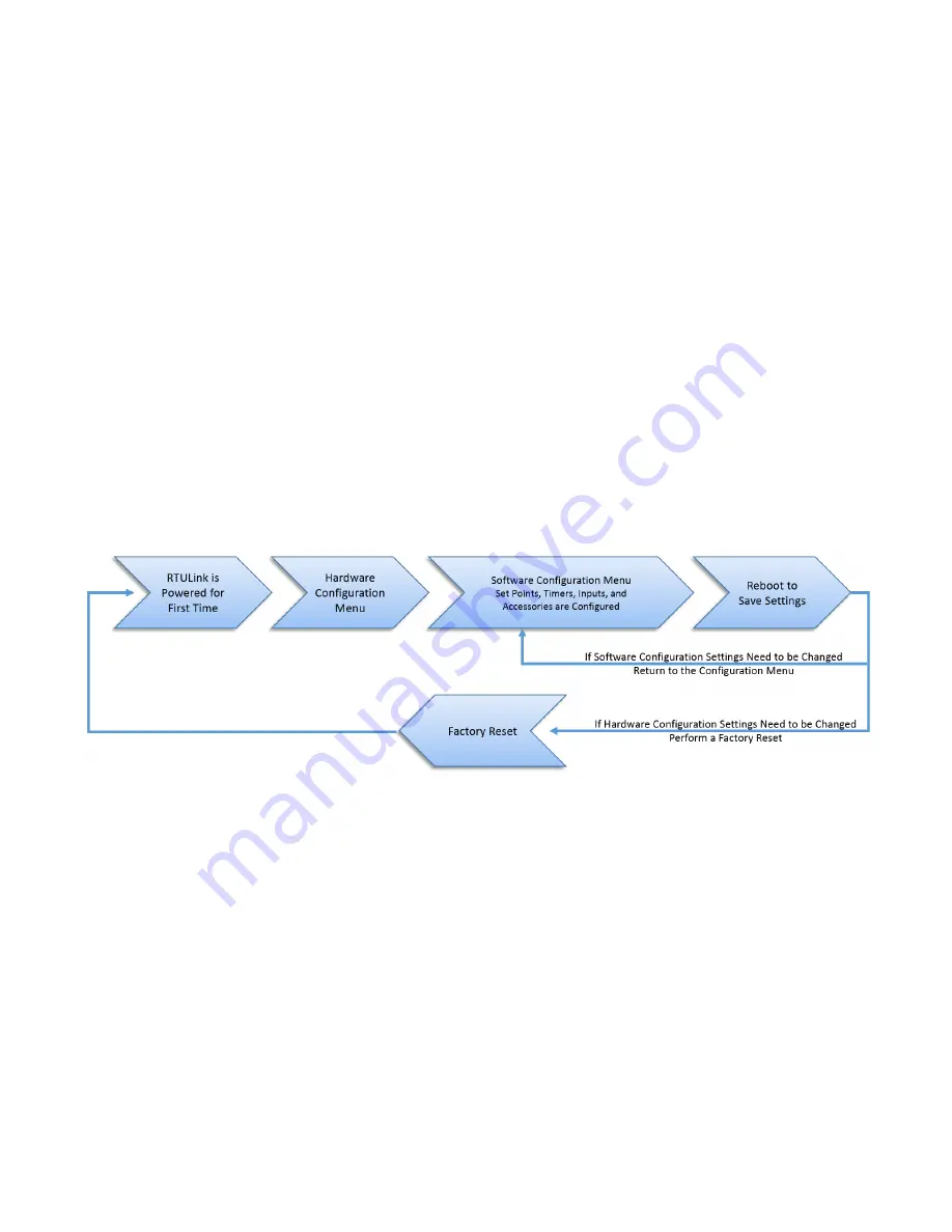
This startup procedure should be followed once the installation procedure has been completed for all RTULinks at the
site. The HMI on the RTULink has four buttons below the screen that are labeled “MENU”, “UP”, “DOWN”, and “ENTER”.
Pressing “MENU” backs out one menu selection and is the opposite of pressing “ENTER”. Pressing “UP” or “DOWN”
cycles through the current menu options. Pressing “ENTER” selects the current menu setting displayed on the HMI.
1. The RTULink should be powered by incoming 24VAC from an RTU transformer. Once powered, the HMI will
power on (indicated by the backlight turning on) and immediately display “START UP CONFIG” in text on the
screen. Press ENTER to move into the Hardware Configuration menu.
2. The Hardware Configuration menu contains parameters that are unique to the hardware of the RTU that the
RTULink is installed in. This menu is treated similar to a setup wizard and is performed only once at the
beginning of the startup procedure. If a hardware configuration parameter is incorrectly set or if the RTULink
board is switched from one RTU to another or if Hardware Configuration parameters need to be changed for
some reason, a “Factory Reset” will need to be performed. Enter and configure the parameters in this menu and
continue once every parameter has been considered.
3.
Once the Hardware Configuration has been set, enter the “Configuration” menu with the password 9002. The
“Configuration” menu contains operational mode settings and parameters. The Control Mode is the second
parameter that will be available in the “Configuration” menu (when cycling down through the menu). The
remainder of the “Configuration” menu will contain parameters exclusive to the control mode that is being utilized.
Examples include timers to reduce cycling, timers to increase energy efficiency, economizer settings, input
configuration, etc. View the mode definitions in the FUNCTIONALITY section of this manual to determine which
operational mode should be utilized.
Figure 27. RTULink System Diagram
Summary of Contents for RTULink
Page 2: ...2...
Page 30: ...30 Main Board HMI Menu Tree...
Page 31: ...31...
Page 32: ...32...
Page 33: ...33...
Page 34: ...34...
Page 41: ...41...
Page 42: ...42...
Page 43: ...43...
Page 44: ...44...
Page 52: ...52 APPENDIX C Fixed Dry Bulb Economizer Figure 34 Fixed Dry Bulb Economizer Operation...
Page 53: ...53 Differential Dry Bulb Economizer Figure 35 Differential Dry Bulb Economizer Operation...
Page 54: ...54 Fixed Enthalpy Economizer Figure 36 Fixed Enthalpy Economizer Operation...
Page 55: ...55 Differential Enthalpy Economizer Figure 37 Differential Enthalpy Economizer Operation...


