background image

Quick Operation Guide of Digital Video Recorder 

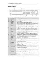
Front Panels 


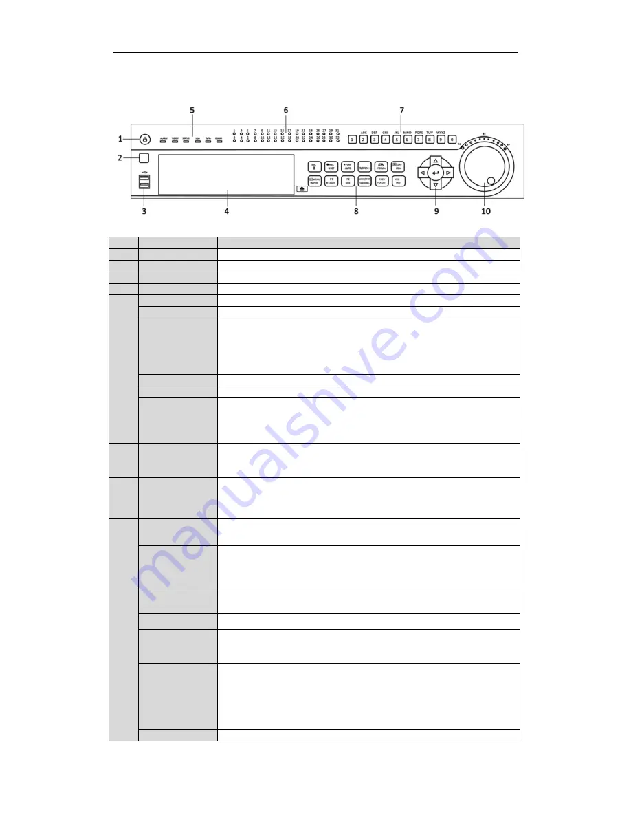
Description of Front Panel 

No. 

Name 

Function Description 

POWER ON/OFF 

Power on/off switch. 

IR Receiver 

Receiver for IR remote control. 

USB 

Connect to USB mouse or USB flash memory devices.


DVD-R/W 

Slot for DVD-R/W.   


ALARM 

Alarm indicator turns red when a sensor alarm is detected. 

READY 

Ready indicator is normally blue, indicating that the DVR is functioning properly. 

STATUS 

Indicator turns blue when DVR is controlled by an IR remote.   
Indicator turns red when controlled by a keyboard and orange when IR remote and 
keyboard is used at the same time. 
Indicator does not light when the DVR is controlled by the IR remote control with 
the address of 255. 

HDD 

HDD indicator blinks in red when data is being read from or written to HDD. 

Tx/Rx


Tx/Rx indictor blinks in blue when network connection is functioning properly. 

GUARD 

Indicator turns blue when the device is armed; 
Indicator does not light when the device is disarmed; 
The arm/disarm state can be initiated by pressing and holding on the ESC button 
for more than 3 seconds in live view mode. 

Channel Status 
LED Indicators       

The button lights in blue when the corresponding channel is recording; it is red 
when the channel is in network transmission status; it is pink when the channel is 
recording and transmitting.   

Alphanumeric 
Buttons 

Switch to the corresponding channel in Live View or PTZ Control mode. 
Input numbers and characters in Edit mode. 
Switch between different channels in All-day Playback mode. 

ESC 

Exit and back to the previous menu. 
Arm/disarm the DVR in live view mode. 

REC/SHOT 

Enter the Manual Record interface.   
Turn audio on/off in Playback mode; 
In PTZ control mode, pressing the REC/SHOT button and a Numeric button will 
call a PTZ preset.     

PLAY/AUTO 

Enter the Playback menu; 
Auto scan in the PTZ Control mode. 

ZOOM+ Button 

In PTZ control mode, the ZOOM+ button is used to zoom in the PTZ camera.   

A/FOCUS+ 

Adjust focus in the PTZ Control mode.   
Switch between input methods (upper and lowercase alphabet, symbols and 
numeric input).


EDIT/IRIS+ 

Edit text fields. When editing text fields, it will also function as a Backspace button 

to delete the character in front of the cursor.   

On checkbox fields, pressing the button will 

tick 

the checkbox.   

In PTZ Control mode, the button adjusts the iris of the camera.   
In Playback mode, it can be used to generate video clips for backup. 

MENU/WIPER 

Return to the Main menu (after successful login);   

Summary of Contents for CW-AR705-4

Page 1: ...Digital Video Recorder Quick Operation Guide...

Page 2: ...Connection 10 RS 485 and Controller Connection 11 Termination Switch Operation 11 Specifications 13 Table 1 Specification 13 HDD Storage Calculation Chart 15 Accessing by Web Browser 16 Logging In 16...

Page 3: ...terference received including interference that may cause undesired operation EU Conformity Statement This product and if applicable the supplied accessories too are marked with CE and comply therefor...

Page 4: ...h Definition Multimedia Interface are trademarks or registered trademarks of HDMI Licensing LLC The products contained in this manual are authorized by HDMI Licensing LLC with the use right of the HDM...

Page 5: ...n or request please do not hesitate to contact dealer This manual is applicable to 2U chassis 1080p real time models of Turbo HD DVR This product has default user name and password credentials for fir...

Page 6: ...imes than its diameter 4 Connect both the alarm and RS 485 cable 5 Allow at least 2cm 0 75 inch of space between racks mounted devices 6 Ensure the DVR is grounded 7 Environmental temperature should b...

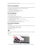
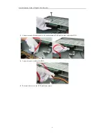
Page 7: ...Guide of Digital Video Recorder 6 3 Connect one end of the data cable to the motherboard of DVR and the other end to the HDD 4 Connect the power cable to the HDD 5 Re install the cover of the DVR and...

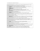
Page 8: ...us LED Indicators The button lights in blue when the corresponding channel is recording it is red when the channel is in network transmission status it is pink when the channel is recording and transm...

Page 9: ...orded video In All day Playback mode the Left Right button can be used to select the recorded video of next previous day in Playback by Normal Video Search the Left Right button can be used to select...

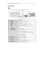
Page 10: ...ay local video output and menu 7 AUDIO OUT RCA connector 8 Network Interface Connector for network 9 RS 485 Interface Connector for RS 485 devices T and T pins connect to R and R pins of PTZ receiver...

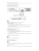
Page 11: ...safely To connect an AC load jumpers should be left open you must remove the jumper on the motherboard in the DVR Use an external relay for safety as shown in the figure above There are 4 jumpers JP1...

Page 12: ...ggable block back into terminal block To connect a controller to the DVR 1 Disconnect pluggable block from the KB terminal block 2 Press and hold the orange part of the pluggable block insert signal c...

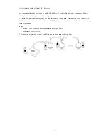
Page 13: ...id the signal reduction caused by the great impedance of long distance transmission please connect two 120 resistors in the circuit one resistor between the DVR and the nearest speed dome and the othe...

Page 14: ...e CIF QCIF QVGA Frame rate Main stream 1 16 fps Real time frame rate Sub stream 1 16 fps Real time frame rate Video bitrate 32 Kbps 10 Mbps Audio output 2 ch RCA Linear 1K for VGA output and CVBS outp...

Page 15: ...Quick Operation Guide of Digital Video Recorder 14 Dimensions W D H 445 470 90 mm 17 5 18 5 3 5 inch Weight without hard disks 8Kg 17 6 lb...

Page 16: ...Bit Rate Storage Used 96K 42M 128K 56M 160K 70M 192K 84M 224K 98M 256K 112M 320K 140M 384K 168M 448K 196M 512K 225M 640K 281M 768K 337M 896K 393M 1024K 450M 1280K 562M 1536K 675M 1792K 787M 2048K 900...

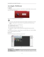
Page 17: ...fari Mozilla Firefox and Google Chrome The supported resolutions include 1024 768 and above The default IP address is 192 0 0 64 The default user name is admin and password is 12345 You are highly rec...

Page 18: ...following table for the description of buttons on the live view window Icon Description Icon Description Select the window division mode Previous page Start Stop all live view Next page Capture pictu...

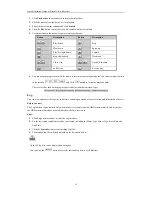
Page 19: ...day to the whole week You can also check any of the checkboxes before the date and click Copy 4 Click OK to save the settings and exit the Edit Schedule interface 6 Click Advanced to configure advance...

Page 20: ...ox and click button to locate the playback point The color of the video on the progress bar stands for the different video types Log You can view and export the log files at any time including operati...

Page 21: ...ceptions Net Detect Video Tampering User Video Loss HDD Detect Image VQD Manual VQD Alarm RS 232 Startup and Shutdown Proper startup and shutdown procedures are crucial to expand the service time of t...

Page 22: ...is an alarm or are alarms Alarm includes video loss tampering motion detection or sensor alarm etc Recording manual record continuous record motion detection or alarm triggered record Alarm Recording...

Page 23: ...ot added is marked in yellow Explanation of the icons Icon Explanation Icon Explanation Edit basic parameters of the camera Add the detected IP camera The camera is connected The camera is disconnecte...

Page 24: ...cord types are introduced in the following section including Instant Record and All day Record And for other record types you may refer to the user manual for detailed information After rebooting all...

Page 25: ...he live view menu OPTION 1 Choose a channel under live view using the mouse and click the button in the shortcut operation menu Only record files recorded during the last five minutes on this channel...

Page 26: ...yback of multiple channels Backup Recorded files can be backed up to various devices such as USB flash drives USB HDDs or USB DVD writers To export recorded files 1 Enter Video Export interface Choose...

Page 27: ...n Detection Line Crossing Detection This function can be used for detecting people vehicles and objects cross a set virtual line The line crossing direction can be set as bidirectional from left to ri...

Page 28: ...ct the Extranet Access tab to enter the Cloud P2P Settings interface 3 Check the Enable Cloud P2P checkbox to activate this feature 4 If required check the Enable Stream Encryption checkbox to encrypt...

Reviews: