background image

52

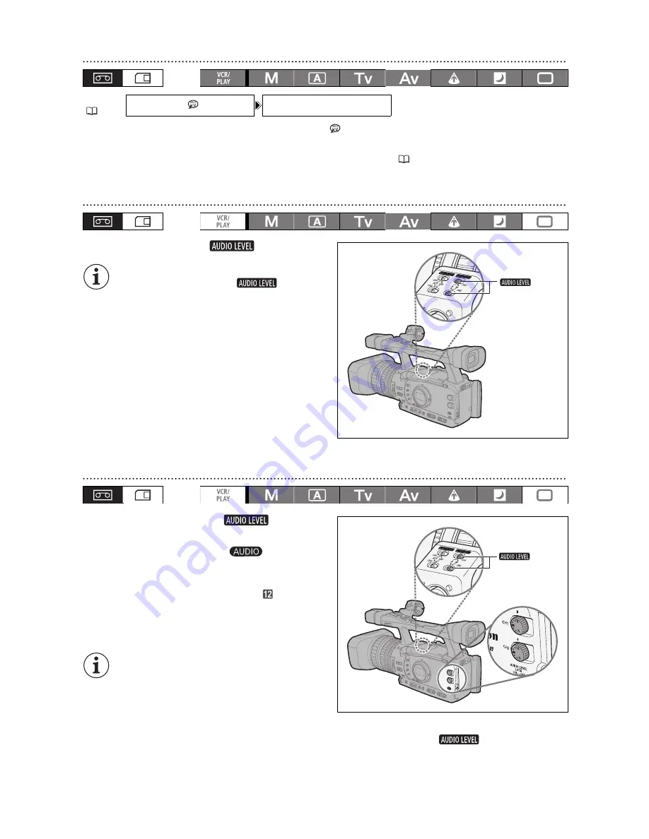
Hiding/Displaying the Audio Level Indicator

Open the menu and select [DISPLAY SETUP/

]. Select [AUDIO LEVEL], select a setting 

option and close the menu.

The audio level indicator can also be turned on/off with a custom key (

73).

Automatic Audio Adjustment

Set the corresponding 

 switch to A.



When [CH1 INPUT] and [CH2 INPUT] are set 
to [INT/EXT MIC], if the 

 switch for 

CH1 is set to A, the automatic audio 
adjustment setting will automatically apply to 
CH2 as well.



When [CH1 INPUT] and [CH2 INPUT] are set 
to [XLR MIC] or [XLR LINE], you can select if 
the audio adjustment setting for CH2 will be 
linked to that of CH1 ([LINK]), or if the settings 
will be separated ([SEP]). 
Open the menu and select [AUDIO SETUP]. 
Select [XLR ALC LINK], select a setting option 
and close the menu.

Manual Audio Adjustment

1. Set the corresponding 

 switch to 

M.

2. Turn the corresponding 

 dial (CH1 or 

CH2) to adjust each channel’s audio level.

Adjust the audio recording level so that the audio 
level meter will go to the right of the


mark on the 

side panel’s audio level meter (or the larger dot on 
the level meter displayed on the screen) only 
occasionally.



We recommend using headphones when 
adjusting the audio level. If the input level is 
too high, audio may become distorted even if 
the audio level indicator shows an 
appropriate level. Use commercially available 
headphones.



When [CH1 INPUT] and [CH2 INPUT] are set to [INT/EXT MIC], if the 

 switch for CH1 is 

set to M, the audio level adjusted with the CH1 dial will automatically apply to CH2 as well.

MENU

(

27)

DISPLAY SETUP/

AUDIO LEVEL••ON

switches

switches

Summary of Contents for XH A1S

Page 1: ...HD Video Camera Recorder Instruction Manual Caméscope et lecteur vidéo HD Manuel d instruction Videocámara y grabadora HD Manual de Instrucciones PUB DIM 894 English Français Español NTSC ...

Page 2: ...to correct the interference by one or more of the following measures Reorient or relocate the receiving antenna Increase the separation between the equipment and receiver Connect the equipment into an outlet on a circuit different from that to which the receiver is connected Consult the dealer or an experienced radio TV technician for help Use of shielded cable is required to comply with class B l...

Page 3: ...perating and maintenance instructions should be followed 17 Cleaning Unplug this product from the wall outlet before cleaning Do not use liquid or aerosol cleaners The product should be cleaned only as recommended in this manual 18 Accessories Do not use accessories not recommended in this manual as they may be hazardous 19 Avoid magnetic or electric fields Do not use the camera close to TV transm...

Page 4: ...ll outlet and all power sources including battery and refer servicing to qualified service personnel under the following conditions a When the power supply cord or plug is damaged b If any liquid has been spilled onto or objects have fallen into the product c If the product has been exposed to rain or water d If the product does not operate normally even if you follow the operating instructions Ad...

Page 5: ...you can easily save and exchange as custom preset files 89 Advanced Professional Features Pro level connectivity An industry standard HD SD SDI terminal for uncompressed HD signal output embedded audio and SMPTE time code LTC are just a few of the features of the XH G1S that give it the functionality of professional broadcast cameras Synchronization Genlock synchronization as well as a TIME CODE t...

Page 6: ...anguage and close the menu If you have mistakenly changed the language follow the mark next to the menu item to change the setting The displays and at the bottom of the screen refer to the names of buttons on the camcorder and will not change regardless of the language selected Setting the Time Zone Daylight Saving Time Set the time zone date and time when you first start using your camcorder or i...

Page 7: ...ra section and recording standards recorder section The video signal can be set to HD high definition or SD standard definition specifications the recording standard on the tape will be HDV or DV respectively Camera Section HD SD Recorder Section HDV DV Playback Signal HDV DV HD SD SDI Terminal HD SD HDV DV Terminal HDV DV only ...

Page 8: ...te 42 Setting the Time Code 44 Synchronizing the Camcorder s Time Code 46 Setting the User Bit 48 Audio Recording 49 Image Stabilizer 54 Using the Programmed AE Modes 55 Recording in Manual Mode 58 Recording in Shutter Priority Tv Mode 60 Recording in Aperture Priority Av Mode 61 Adjusting the Exposure 62 AE Shift 62 Gain 63 White Balance 65 Zebra Pattern 67 Color Correction 68 Skin Detail Functio...

Page 9: ... Images on a Memory Card 114 Reviewing a Still Image Right After Recording 116 Drive Mode 117 Metering Mode 118 Using an Optional Flash 119 Playing Back Still Images from a Memory Card 120 Erasing Still images 122 Protecting Still images 123 Initializing a Memory Card 124 Print Order Settings 125 Additional Information Menu Options and Default Settings 126 Settings Memorized and Retained 135 Scree...

Page 10: ... Video Cable Adjustment Band for the external microphone holder Tripod Adapter Base SS 1100 Shoulder Strap Lens Cap Lens Hood Eye Cup The serial number of this product can be found at the battery attachment unit of the camcorder Write down the number and other information here and retain this book as a permanent record of your purchase to aid identification in case of theft Date of Purchase Model ...

Page 11: ...ch 37 POSITION PRESET ON SET switch 36 40 ND FILTER switch 41 Iris ring 58 61 POWER indicator Side panel 138 OPEN open the LCD display switch 20 CH1 CH2 dials 51 AUDIO LEVEL LOCK switch 51 SELECT SET dial 27 volume dial 108 MENU button 27 Focus ring 37 Zoom ring 35 SHUTTER dial 60 dial 66 PUSH AF button 37 EXP LOCK button 62 PUSH AE button 59 GAIN switch 63 AGC automatic gain control switch 63 OUT...

Page 12: ...terminal 81 HD SD SDI terminal 79 GENLOCK terminal 46 TIME CODE terminal 46 MIC external microphone terminal 49 switches 50 switches 52 Lens hood 22 Lens hood locking screw 22 switches 51 CH1 input terminal 50 CH2 input terminal 50 Cassette compartment 25 TIME CODE switch 46 ...

Page 13: ...nnected devices may not operate or may operate differently than the buttons on the camcorder Front view Back view External microphone holder 50 Tally lamp 102 External sensor for the Instant AF 37 Grip belt 22 Attachment sockets for the optional TA 100 Tripod Adapter 148 or the supplied tripod adapter base Microphone lock screw 21 Remote sensor 24 111 Tripod socket Viewfinder 19 OPEN open the batt...

Page 14: ...button 120 REC record button 86 START STOP button 30 LOCK switch 31 OPEN EJECT switch 25 Grip zoom lever 35 PHOTO button 114 MAGN button 39 Zoom speed adjustment dial 35 RESET button Speaker 108 MIC ATT switch 51 WHITE BAL PRESET switch 65 END SEARCH button 34 Strap mount 22 Microphone 49 Strap mount 22 Hot shoe 119 Handle zoom lever 35 PHOTO button 114 MAGN button 39 LCD panel 20 ...

Page 15: ...button 83 END SEARCH button 34 SEARCH SELECT button 109 110 REC PAUSE button 86 REW button 107 ZERO SET MEMORY button 109 button 107 PAUSE button 107 REMOTE SET button 111 AV DV button 87 Zoom buttons 35 Menu selection buttons 27 SET button 27 CARD button 120 CARD button 120 MIX BALANCE buttons 83 buttons 109 110 PLAY button 107 FF button 107 button 107 STOP button 107 button 107 SLOW button 107 ...

Page 16: ... completed 4 When the charging is completed remove the battery pack from the compact power adapter 5 Unplug the power cord from the power outlet and disconnect it from the compact power adapter Attaching the Battery Pack 1 Turn the dial to OFF 2 Push the OPEN switch in the direction of the arrow to open the battery compartment cover 3 Insert the battery all the way into the compartment and press g...

Page 17: ...wer adapter when charging a battery pack Turn off the camcorder before connecting or disconnecting the compact power adapter If the compact power adapter is used close to a TV it may cause picture interference Move the compact power adapter away from the TV or the antenna cable Do not connect to the compact power adapter any products not expressly recommended for use with this camcorder If you con...

Page 18: ...460 min Typical Recording Time Viewfinder NORMAL 95 min 145 min 205 min 295 min Viewfinder BRIGHT 95 min 145 min 205 min 295 min LCD screen NORMAL 95 min 140 min 200 min 275 min LCD screen BRIGHT 90 min 140 min 195 min 280 min Playback Time LCD screen NORMAL 175 min 265 min 370 min 530 min Recording and Playback Times BP 930 BP 945 BP 950G BP 970G Maximum Recording Time Viewfinder NORMAL 155 min 2...

Page 19: ...p so that the protruding portion faces the opposite side Detaching the Eye Cup Detach the eye cup as shown in the illustration Dioptric Adjustment Turn on the camcorder and adjust the dioptric adjustment lever Do not let the viewfinder be exposed to direct sunlight or other strong light sources The viewfinder LCD may become damaged due to concentration of the light by the lens Pay special attentio...

Page 20: ... of the viewfinder LCD display These adjustments will not affect your recording The default value is BRIGHT while using the power adapter 1 Press the MENU button 2 Turn the SELECT SET dial to select DISPLAY SETUP and press the dial 3 Select CVF SETUP to adjust the viewfinder or LCD SETUP to adjust the LCD display and then select BRIGHTNESS CONTRAST COLOR SHARPNESS or BACKLIGHT 4 Adjust the setting...

Page 21: ...ite display mode 1 Press the MENU button 2 Turn the SELECT SET dial to select DISPLAY SETUP and press the dial 3 Select CVF LCD BW set it to ON and press the dial 4 Press the MENU button to close the menu Attaching an External Microphone 1 Loosen the microphone lock screw on the viewfinder unit open the microphone holder and insert the microphone 2 Tighten the lock screw 3 Plug the microphone cabl...

Page 22: ...careful not to drop the camcorder when adjusting the strap or the grip belt Attaching the Lens Hood Attach the lens hood to protect the lens and shade it from stray light 1 Place the lens hood on the front of the lens so that the window for the external Instant AF sensor faces down and turn it 90 degrees clockwise Be careful not to deform the lens hood Make sure that the lens hood is aligned with ...

Page 23: ...his step is not necessary for the HD SD SDI terminal and VIDEO 2 terminal Closing the Terminal Covers Insert into the opening the strip connecting the cover to the camcorder and close the terminal If the connecting strip is difficult to grasp use a pair of tweezers or similar tool HD SD SDI terminal GENLOCK terminal TIME CODE terminal VIEWFINDER COMPONENT OUT terminal HD SD COMPONENT OUT terminal ...

Page 24: ...e camcorder and wireless controller are equipped with 2 remote sensor modes 111 If the wireless controller does not work verify that the camcorder and wireless controller are set to the same mode When the camcorder cannot be operated with the wireless controller or when it can only be operated at very close range replace the batteries Make sure to replace both batteries at the same time The wirele...

Page 25: ...ight fully into the compartment with the window facing out Remove the cassette by pulling it straight out 3 Close the cassette compartment by pressing on the mark on the cover The cassette compartment will retract automatically 4 Close the cassette compartment cover Do not interfere with the cassette compartment while it is opening or closing automatically Be careful not to get your fingers caught...

Page 26: ... indicator is not flashing and set the dial to OFF 2 Push the OPEN switch in the direction of the arrow to open the battery memory card compartment cover 3 Push the memory card once to release it and then remove the memory card 4 Close the compartment If you use memory cards other than the supplied one make sure to initialize them with the camcorder 124 Turn off the camcorder before inserting or r...

Page 27: ... to close the menu The and icons displayed at the bottom of the screen will give you additional indications about the function of these controls in specific situations You may find it more convenient to use the wireless controller to operate the menu Press the MENU button on the wireless controller to open or close the menu Use the menu selection buttons of the wireless controller instead of the S...

Page 28: ...t SYSTEM SETUP and press the dial 3 Select D TIME SET and then select T ZONE DST and press the dial The time zone setting appears The default setting is New York 4 Turn the SELECT SET dial to select the setting option that matches your time zone and press the dial To adjust for daylight saving time select the time zone marked with a Setting the Date and Time 5 Select DATE TIME and press the dial T...

Page 29: ...GUIDE INFO set it to D T DISPLAY and close the menu Changing the Date Format You can select between three date formats JAN 1 2008 1 JAN 2008 and 2008 1 1 Open the menu and select SYSTEM SETUP Select the D TIME SET submenu and then select DATE FORMAT Select a date format and close the menu MENU 27 DISPLAY SETUP GUIDE INFO OFF MENU 27 SYSTEM SETUP D TIME SET DATE FORMAT JAN 1 2008 ...

Page 30: ...sconnect the power source The end search date search and index search functions may not work correctly if you mix recordings in HDV and DV standards on the same tape We recommend not mixing recordings in different standards on the same tape After inserting a cassette wait until the tape counter stops completely before you start recording Turn the dial to OFF if you do not intend to use the camcord...

Page 31: ...tments without worrying about losing your settings as a result of the automatic shut off Once the camcorder entered the power save mode press the START STOP button to start recording or press one of the custom keys 73 to which the VCR STOP function was assigned to return to record pause mode If the camcorder automatically shut off after 5 minutes turn the dial to OFF and then back to one of the re...

Page 32: ...r of minutes that appears on the cassette s label for example 85 minutes Remaining battery charge The battery symbol indicates the charge status of the battery pack starts flashing in red when the battery pack is empty When you attach an empty battery pack the power may turn off without displaying The actual battery charge may not be indicated accurately depending on the condition under which the ...

Page 33: ...ot be selected if DISPLAY SETUP MARKERS SAFETY ZONE and GUIDE INFO are all set OFF The camcorder s on screen displays will also appear on a connected external TV or monitor Reviewing the Recording In record pause mode this function allows you to review the last few seconds of your recording Press and release the record review button The camcorder rewinds the tape plays back the last few seconds an...

Page 34: ...tandard definition SD camera Select the aspect ratio as desired When you play back 16 9 recordings the TV set will switch automatically to widescreen mode if it is compatible with the Video ID 1 system Otherwise change the aspect ratio of the TV manually To play back on a standard TV set with 4 3 aspect ratio set SIGNAL SETUP LETTERBOX to ON 126 Locating the End of the Last Scene You can use this ...

Page 35: ...he arrow FAST to select a faster zoom speed level higher number turn it the other way to select a slower zoom speed level lower number When the ZOOM SPEED switch is set to VAR variable the zoom speed will depend on how you operate the zoom lever press gently for a slower zoom press harder for faster zooms Approximate zoom speeds 1 Default setting when recording movies in Easy Recording mode When r...

Page 36: ...iven zoom position to be memorized Later you can return to the preset zoom position instantly Presetting the Zoom 1 Set the POSITION PRESET switch to ZOOM 2 Move the POSITION PRESET ON SET switch to SET The preset zoom position appears in yellow on the zoom indicator Returning to the Preset Zoom Position Move the POSITION PRESET ON SET switch to ON The camcorder returns to the preset zoom position...

Page 37: ...ont of the lens barrel to The camcorder focuses on the subject in the center of the screen Follow the procedure below to change the autofocus mode Open the menu and select CAMERA SETUP Select AF MODE select a setting option and close the menu INSTANT AF The focus is adjusted at the highest speed This mode is useful even when recording in very bright or low light surroundings The TTL system and the...

Page 38: ... manually and then leave the camcorder with the power turned on the focus on the subject may be lost after a while This possible slight shift in focus is a result of the internal temperature rising in the camcorder and lens Check the focus before resuming shooting Manual focus cannot be selected in Easy Recording mode Even if you set the focus mode switch to M the autofocus Instant AF will still b...

Page 39: ...your recordings The gain and frequency of peak levels and can be set independently with the DISPLAY SETUP PEAKING SETUP setting Magnifying In record pause press the MAGN button MAGN appears and the central part of the screen will be magnified approximately 2x Press the button again to cancel the function The magnified picture will be output as is to the HD SD SDI terminal only and the HDV DV termi...

Page 40: ...us Preset Speed Open the menu and select CAMERA SETUP Select F SPEED PSET select a setting option and close the menu 4 is the fastest speed 1 is the slowest Returning to the Preset Focus position Move the POSITION PRESET ON SET switch to ON The camcorder returns to the preset focus position Focus Limit and Macro Shooting Usually the camcorder s focus range allows macro shooting You can activate th...

Page 41: ...set a smaller aperture Depending on the scene the color may change when turning the ND filter on off Setting a custom white balance may be effective in such case 66 Screen display What it means What you should do No display ND filter is not activated ND ND filter is activated ND flashes ND filter required Turn on the ND filter ND flashes Higher density setting or external ND filter required Set th...

Page 42: ...SD COMPONENT OUT terminal the signal will be down converted to 60i using the 2 3 pulldown method 24F 2 3 Mode Signals are down converted to 60i using the 2 3 pulldown method This 24F mode is suited for playback on a TV screen but may require the extension compression of some frames while editing 24F 2 3 3 2 Mode Signals are down converted to 60i using the 2 3 3 2 pulldown method This 24F mode is i...

Page 43: ...ting option and close the menu 2 3 24F appears in white 2 3 3 2 24F appears in orange If you are using an editing system that does not support the 2 3 3 2 pulldown method make sure to record in 24F 2 3 pulldown mode Video recorded in 24F or 30F can only be played back with compatible devices and can only be edited with software that supports these frame rates For software and hardware compatibilit...

Page 44: ... and then COUNT UP Select a setting option and close the menu REC RUN Close the menu REC RUN PS FREE RUN Continue the procedure to set the initial value 2 Select SET The hours display flashes 3 Set the time code s initial value Turn the SELECT SET dial to set the value for the hours and press the dial Set the value for the minutes seconds and frames in the same way 4 Close the menu About the time ...

Page 45: ...rop frame time codes including 24F frame rate in SD mode there might be a discontinuity in the time code at the point where the recording starts When recording over existing scenes When a time code discontinuity occurred near the recording start point the time code at the point where the recording starts may be discontinuous as well As long as the built in rechargeable lithium battery is charged t...

Page 46: ...SDI terminal When SIGNAL SETUP UB OUT is set to HD 24P 2 3 the user bit of the time code signal will be 2 3 pulldown data when recording in 24F mode or playing back movies that are HDV 1080 24p In other words when recording in 24F mode or playing back movies that are HDV 1080 24p the signal is converted to 60i using the 2 3 pulldown method and output from the HD SD SDI terminal An external device ...

Page 47: ... to the TIME CODE COUNT UP settings will be recorded on the tape instead If the external Genlock signal is incorrect or there is no input signal the external time code being recorded on tape may be incorrect When recording in SD mode Time Code IN is not available if you select the 24F frame rate the mode will be canceled and the TC IN OUT display on the side panel will disappear When the camcorder...

Page 48: ...lected 00 00 00 00 2 Select SET The first character of the user bit flashes 3 Turn the SELECT SET dial to select a number or letter and press the dial The next character of the user bit starts flashing Set the rest of the user bit in the same way 4 Close the menu To reset the user bit to 00 00 00 00 select CLEAR in step 2 The user bit can be recorded when recording with the camcorder or from analo...

Page 49: ...ophone s Audio Recording Mode You can select the most appropriate setting given your recording conditions for recording audio with the built in microphone Open the menu and select AUDIO SETUP Select LOW CUT select a setting option and close the menu OFF To record audio under usual conditions LC1 To record mainly people s voices LC2 To reduce the background sound of wind when recording outdoors in ...

Page 50: ...nal Microphone When you connect an external microphone to the MIC terminal the built in microphone will automatically be turned off If necessary you can use the microphone holder External Microphones that can be Connected Microphone Type Condenser microphones with independent power supply Type of Plug 3 5 mm Input Impedance 600 ohms Sensitivity 66 dBV manual volume center Maximum microphone diamet...

Page 51: ...corresponding switch to ATT The microphone attenuator will only be effective when the input is set to XLR MIC 5 If necessary adjust the gain of the input signal Open the menu and select AUDIO SETUP Select XLR 1 TRIM or XLR 2 TRIM depending on the audio input you want to adjust Select a setting option and close the menu The gain adjustment will only be effective when the input is set to XLR MIC Whe...

Page 52: ...UDIO SETUP Select XLR ALC LINK select a setting option and close the menu Manual Audio Adjustment 1 Set the corresponding switch to M 2 Turn the corresponding dial CH1 or CH2 to adjust each channel s audio level Adjust the audio recording level so that the audio level meter will go to the right of the mark on the side panel s audio level meter or the larger dot on the level meter displayed on the ...

Page 53: ...t manually Embedded Audio Embedded audio refers to the superimposing of the audio signal along with the video signal being output from the HD SD SDI terminal ON To embed the audio ON OSD To embed the audio and on screen displays Open the menu and select SIGNAL SETUP Select SDI OUTPUT select a setting option and close the menu The embedded audio output depends on the signal standard and the samplin...

Page 54: ...close the menu The image stabilizer cannot be turned off in the Easy Recording mode We recommend turning off the image stabilizer when the camcorder is mounted on a tripod The image stabilizer is designed to compensate for a normal degree of camcorder shake The image stabilizer will have increased effectiveness while half pressing the PHOTO button to lock the autofocus MENU 27 CAMERA SETUP IMG STA...

Page 55: ...er automatically sets the appropriate aperture value Aperture Priority 61 Use this mode to select the aperture value from F 1 6 to F 9 5 or full iris close and let the camcorder automatically set the appropriate shutter speed This mode allows for the best control of depth of field Spotlight The Spotlight mode automatically adjusts the exposure to effectively record images and or subjects lit by a ...

Page 56: ...ble Selecting the Programmed AE Modes Press the lock button and turn the dial The symbol of the selected mode appears Do not change the position of the dial while recording as the brightness of the image may change abruptly The Easy Recording Spotlight and Night modes are all automatic modes In the Auto Tv Shutter Priority Av Aperture Priority and M Manual modes you can change some settings manual...

Page 57: ...r scan EXP LOCK button PUSH AE button Iris ring 1 1 SHUTTER dial 1 1 AE shift adjustment 0 GAIN adjustment 0 dB AGC ON WHITE BALANCE adjustment auto Custom preset adjustments CUSTOM PRESET SELECT button CUSTOM PRESET ON OFF button Skin detail Selective NR Color correction Clear scan 2 2 Frequency selection for clear scan ...

Page 58: ...n use the custom keys 73 or the SYSTEM SETUP SHTR D LOCK setting 130 to prevent the accidental operation of the SHUTTER dial With the custom function IRIS LIMIT 97 you can activate the iris limit to prevent the aperture from closing below the diffraction limit of the lens If the iris limit is not activated aperture values that exceed the diffraction limit will appear in gray when selecting the ape...

Page 59: ...djusting the aperture and gain if the AGC switch is set to ON Press the PUSH AE button and hold it pressed down The camcorder will adjust the aperture value and gain to achieve optimal exposure mark above the exposure indicator After you release the button the aperture value and gain if the AGC switch is set to ON set by the camcorder will override the previous settings made in M Manual mode You c...

Page 60: ...N the numeric value on the screen flashes if the selected shutter speed is not suitable for the recording conditions In such case readjust the shutter speed If you are using an ND filter turn it off first and readjust the shutter speed Image quality may decrease to some extent when using slow shutter speeds When recording under artificial light sources such as fluorescent mercury or halogen lamps ...

Page 61: ...change the aperture overriding the value selected in Av mode When the AGC switch is set to ON the numeric value on the screen flashes when the selected aperture is not appropriate for the recording condition In such case readjust the aperture When the built in ND filter is activated the picture may become dark when you set a high aperture value In such case turn off the ND Filter first and readjus...

Page 62: ... beyond 2 stops the marker will blink You can use the custom keys 73 or the SYSTEM SETUP E LCK B LCK setting to prevent the accidental operation of the EXP LOCK button AE Shift You can use the AE Shift control to manually override the automatic exposure system in order to darken or lighten the image Select from 15 AE levels 2 0 1 5 1 25 1 0 0 75 0 5 0 25 0 0 25 0 5 0 75 1 0 1 25 1 5 2 0 1 Set the ...

Page 63: ...to the GAIN Switch Positions 1 Set the dial to M Tv or Av 2 Open the menu and select CAMERA SETUP Select the GAIN SETTING submenu and then one of the GAIN switch options 3 Select a setting option and press the SELECT SET dial After the adjustment you will return to the GAIN SETTING submenu Assign the gain values to the other GAIN switch options in the same way 36dB is available only in mode 4 Clos...

Page 64: ...2 Set the AGC switch to OFF 3 Set the GAIN switch to the desired gain position When you select high gain levels the picture may flicker slightly The 36 0 dB gain level in particular allows you to shoot video with a higher sensitivity but is more prone to the appearance of noise and artifacts white dots vertical streaks or blocking When the AGC switch is set to ON you can activate the gain limit to...

Page 65: ...itch to OFF and the WHITE BAL switch to PRE 3 Set the WHITE BAL PRESET switch to or You can also fine tune the preset settings Press the WHITE BAL button so the preset icon starts flashing and the neutral value 0 appears next to it Adjust the white balance with the dial to a value between 9 and 9 and press the WHITE BAL button again White balance setting Use AWB Automatic adjustment of white balan...

Page 66: ...ce Very rarely and depending on the light source may keep flashing The result will still be better than with automatic white balance As long as the built in rechargeable lithium battery is charged the camcorder retains the custom white balance setting even if you turn it off The following custom preset settings take precedence and will override the white balance set with the procedure above The co...

Page 67: ...ot be displayed while the Peaking function is activated 39 Available zebra pattern settings 70 IRE 75 IRE 80 IRE 85 IRE 90 IRE 95 IRE and 100 IRE Selecting the Zebra Pattern Level Open the menu and select DISPLAY SETUP Select ZEBRA LEVEL select a setting option and close the menu Activating the Zebra Pattern Open the menu and select DISPLAY SETUP Select ZEBRA set it to ON and close the menu MENU 2...

Page 68: ...ed 6 orange 9 green 12 blue CHROMA Adjust the color saturation for the color to be detected 13 levels 6 to 6 are available set higher levels to detect areas with richer colors AREA Adjust the color range for the color to be detected 4 levels 1 to 4 are available set higher levels to detect a wider color range Y LEVEL Adjust the brightness for the color to be detected 13 levels 6 to 6 are available...

Page 69: ...e menu and select CAMERA SETUP and select the COLOR CORR submenu 2 Select CORRECT select a correction mode and close the menu You can correct only the predefined A area only the predefined B area or both appears MENU 27 CAMERA SETUP COLOR CORR CORRECT OFF ...

Page 70: ...e menu HUE Adjust the hue for detection of the skin area 13 levels 6 to 6 are available set values to detect hues closer to green or values to detect hues closer to red CHROMA Adjust the color saturation for detection of the skin area 13 levels 6 to 6 are available set higher levels to detect areas with richer colors AREA Adjust the color range for detection of the skin area 13 levels 6 to 6 are a...

Page 71: ...evels as necessary and close the menu HUE Select the base hue 6 to 6 of the color to be detected Use the following values as an approximate reference 6 blue violet 0 cyan 6 yellowish green CHROMA Adjust the color saturation for the color to be detected 13 levels 6 to 6 are available set higher levels to detect areas with richer colors AREA Adjust the color range for the color to be detected 13 lev...

Page 72: ...n You can adjust the frequency from 60 1 Hz to 203 9 Hz 1 Set the dial to M or Tv 2 Turn the SHUTTER dial to set the shutter speed to CS 3 Open the menu and select CAMERA SETUP Select CLEAR SCAN adjust the frequency and close the menu Adjust the frequency so that the black band does not appear MENU 27 CAMERA SETUP CLEAR SCAN 60 1Hz SHUTTER dial ...

Page 73: ...ted with a custom key Index write can also be operated with the wireless controller 3 only CUSTOM KEY 1 TIME CODE TV SCREEN ZEBRA TV SCREEN CUSTOM KEY 2 INDEX WRITE DATA CODE TV SCREEN CVF LCD BW Time code Index write 2 Zebra pattern VCR stop 2 TV screen Time code hold 2 Audio level Viewfinder and LCD B W mode MAGN button lock SHUTTER dial lock EXP LOCK button lock CP backward key 1 2 SDI output 3...

Page 74: ...ignal cannot be added or erased later ZEBRA Zebra Pattern 67 Press the CUSTOM KEY 1 or 2 button The zebra pattern is activated Press the button again to cancel it VCR STOP VCR Stop 31 When the camcorder is in record pause mode you can turn off the recorder section Even if SYSTEM SETUP POWER SAVE is set to OFF you can take your time adjusting the camera settings while the recorder section of the ca...

Page 75: ... between recording and playback or change the position of the card tape switch AUDIO LEVEL Audio Level Indicator 52 Press the CUSTOM KEY 1 or 2 button The audio level indicator appears Press the button again to hide the audio level indicator CVF LCD BW Viewfinder and LCD Screen s Black White Display Press the CUSTOM KEY 1 or 2 button The image on the screen will be shown in black white on screen d...

Page 76: ...eys SDI OUTPUT SDI Output Press the CUSTOM KEY 1 or 2 button The SDI output setup menu appears FOCUS LIMIT Focus Limit 40 Press the CUSTOM KEY 1 or 2 button The focus limit is activated Press the button again to cancel it IMAGE STAB Image Stabilizer 54 Press the CUSTOM KEY 1 or 2 button The image stabilizer is activated Press the button again to cancel it OUTPUT CH Output Channel 83 Press the CUST...

Page 77: ...select the strength of the audio signal 12 dB 18 dB or 20 dB 1 Select the standard of the color bars signal COLOR BARS and the strength of the audio reference signal 1kHz TONE with the customized functions 97 2 Set the OUTPUT switch to BARS The color bars appear and the audio reference signal is emitted if activated Press the START STOP button to record the signal If you set 1kHz TONE to OFF the c...

Page 78: ...e video output even if SIGNAL SETUP SDI OUTPUT is set to ON OSD 7 On screen displays will not be embedded in the video output even if DISPLAY SETUP TV SCREEN is set to ON 8 Converted to 60i 9 Converted to 60i using the 2 3 pulldown method 10 When a time code signal is output from the TIME CODE or HD SD SDI terminal the user bit for this signal can be set to 2 3 pulldown data 42 11 Converted to 60i...

Page 79: ...PONENT OUT Terminals HDV DV Terminal A V1 and VIDEO 2 Terminals HD LETTERBOX set to OFF 1920x1080 D3 1440x1080 2 MPEG TS LETTERBOX set to ON SD SDI D1 SD MPEG TS SD 16 9 LETTERBOX set to OFF 640x480 D1 SD DV SD LETTERBOX set to ON SD SDI D1 SD DV SD SD 4 3 640x480 D1 SD Normal DV SD 1 R L AUDIO VIDEO INPUT STV 290N Stereo Video Cable supplied BNC Cable commercially available Signal flow Signal flo...

Page 80: ...el grid markers etc are never included in the video signal output The SIGNAL SETUP COMP OUT setting is not available Using the HD SD COMPONENT OUT or VIEWFINDER COMPONENT OUT Terminal Use the HD SD COMPONENT OUT terminal to monitor the video that the camcorder is recording and use the VIEWFINDER COMPONENT OUT terminal to monitor the picture on the viewfinder screen When using the HD SD COMPONENT O...

Page 81: ... household power outlet TV sets equipped with the Video ID 1 System Recordings made with a 16 9 aspect ratio 34 will be played automatically in widescreen mode whether you connect the camcorder to the TV using the A V1 terminal or the VIDEO 2 terminal During fast forward playback rewind playback and reverse playback of a tape recorded in HDV standard the picture may be distorted 3 CV 250F DV Cable...

Page 82: ...m in the previous section 81 If connecting to a TV set with a 4 3 aspect ratio change the LETTERBOX setting appropriately Open the menu and select SIGNAL SETUP Select LETTERBOX set it to ON and close the menu We recommend powering the camcorder from a household power outlet TV sets equipped with the Video ID 1 System Recordings made with a 16 9 aspect ratio 34 will be played automatically in wides...

Page 83: ...erminal from 1 Vrms to 2 Vrms 6 dB Open the menu and select AUDIO SETUP Select OUTPUT LEVEL select a setting option and close the menu The output level from the headphone terminal does not change Selecting the Audio Monitor Open the menu and select AUDIO SETUP Select AUD M SET select a setting option and close the menu You can also select the audio monitor using the wireless controller If you sele...

Page 84: ...CH1 CH1 CH1 CH1 CH CH CH2 CH2 CH2 CH2 ALL CH ALL CH CH1 CH2 CH1 CH2 CH1 CH2 CH1 CH2 CH CH CH CH3 CH4 CH CH CH3 CH3 CH CH CH4 CH4 ALL CH ALL CH CH3 CH4 CH3 CH4 MIX FIXED CH CH CH1 CH3 CH2 CH4 Fixed 1 1 CH CH CH1 CH3 CH1 CH3 CH CH CH2 CH4 CH2 CH4 ALL CH ALL CH CH1 CH2 CH3 CH4 CH1 CH2 CH3 CH4 MIX VAR CH CH CH1 CH3 CH2 CH4 Variable CH CH CH1 CH3 CH1 CH3 CH CH CH2 CH4 CH2 CH4 ALL CH ALL CH CH1 CH2 CH3 ...

Page 85: ...as the external device continues recording While both this camcorder and a connected device are recording if this camcorder stops recording because of a condition other than pressing the START STOP button e g if the tape has reached its end the connected device will continue recording When this camcorder stops recording you may notice a brief interruption of the audio on the connected device The s...

Page 86: ...less controller when the scene you wish to record appears Recording starts 6 Press the button to stop recording Analog Line In 1 Open the menu and select AUDIO SETUP Select DV AUDIO select a setting option and close the menu 2 Connect the camcorder to the output terminals of the analog video device For the connection diagram to an analog device refer to Section of Connecting to a Monitor TV 81 3 P...

Page 87: ...al signals might not work properly e g signals that include copyright protection signals or anomalous signals such as ghost signals For normal use set AV DV to OFF If it is set to ON digital signals cannot be input via the camcorder s HDV DV terminal Depending on the software and the specifications of your computer you may not be able to transfer converted signals via the HDV DV terminal We recomm...

Page 88: ...hat the computer s video capturing system is compatible with the video signal standard you are using If the computer is not compatible with the camcorder s video output signal the camcorder may not be correctly detected or may not operate properly Refer also to the instruction manual of the computer and the editing software Adjust the SIGNAL SETUP PLAYBACK STD and HD DOWN CONV settings in accordan...

Page 89: ...n XL H1S XL H1A XH G1 or XH A1 can be used with this camcorder Custom preset files saved with this camcorder can be used on a Canon XL H1S XL H1A XH G1 or XH A1 Custom preset files 7 to 9 on the camcorder are predefined custom preset files especially designed for specific scenes Custom Preset Parameters Available only when recording movies GAM Gamma curve Group 1 Parameters related to light and gr...

Page 90: ...een Repeat this step to adjust all the parameters you want to change 6 When you finish adjusting all the parameters you want to change in the custom preset file select RETURN press the dial and close the menu The custom preset parameters appear in one screen as 3 letter abbreviations followed by the current setting value As you move between the items with the SELECT SET dial the full name of the c...

Page 91: ...en 4 Close the menu Protecting a Custom Preset File Follow steps 1 3 in Changing Custom Preset Parameters 90 to select the custom preset file you want to protect 1 From the bottom bar select PROTECT The protection mark will appear next to the custom preset file name To cancel the protection repeat the procedure for a custom preset file with the mark Resetting a Custom Preset File Follow steps 1 3 ...

Page 92: ...the bottom bar select SELECT CP and then select the name of the custom preset file you want to copy to the card 4 Select SAVE POSITION and select the file name under which you want to store the file on the memory card Up to 20 custom preset files can be stored on the memory card If you try to save more than 20 custom preset filed one of the files on the card will be overwritten you can select whic...

Page 93: ...e confirmation screen select EXECUTE to load the file 6 Close the menu Custom preset files 7 to 9 are predefined settings designed for specific scenes These 3 custom preset files are protected and as long as the protection is not removed cannot be overwritten Even if you deleted or changed the sample custom preset files you can reset them to the original values by resetting all the camcorder s set...

Page 94: ...ster Pedestal Adjust the master pedestal level in the range 9 to 9 The master pedestal lowers or raises the baseline of the luminance signal affecting only the shadow areas Set values to subdue the dark areas or set values to get more detail in the shadows SET Setup Level Adjust the setup level in the range 9 to 9 The setup level lowers or raises the whole gamma curve controlling the darkest level...

Page 95: ...much When picture noise is already low due to the gain settings the noise reduction function may not be noticeable When activated settings other than OFF moving subjects may leave a trailing afterimage NR2 Noise Reduction 2 You can select from OFF HIGH MIDDLE or LOW to reduce the noise caused by shooting fast moving objects Results in an effect similar to applying the skin detail function over the...

Page 96: ...e level in the range 50 to 50 GRM G R Matrix The G R matrix changes the tint of the picture along the magenta red and green cyan gradations without affecting blues Adjust the level in the range 50 to 50 GBM G B Matrix The G B matrix changes the tint of the picture along the magenta blue and green yellow gradations without affecting reds Adjust the level in the range 50 to 50 BRM B R Matrix The B R...

Page 97: ...RN and press the SELECT SET dial 3 From the bottom bar select TUNE The first function 00 of the custom function file will be highlighted in blue 4 Turn the SELECT SET dial to select a function you want to adjust and press the dial Make the selection as necessary and press the dial Repeat this step to adjust all the functions you want to change 5 When you finish adjusting all the functions in the c...

Page 98: ...le to the Memory Card 1 Open the menu select CUSTOMIZE and then select the CUSTOM FUNCTION submenu 2 From the column on the left select the custom function file you want to copy to the memory card 3 From the bottom bar select SAVE TO CARD 4 Select the destination file on the memory card 1 3 5 Select OK press the SELECT SET dial and close the menu When the operation is finished TASK COMPLETED will ...

Page 99: ...OM RING CTRL NORMAL 03 ZOOM SPEED NORMAL 04 FOCUS RING CTRL 05 BUTTONS OPER 1 MAGN WB SET PUSH AF 06 BUTTONS OPER 2 REC REVIEW END SEARCH 07 RINGS DIRECTION ZOOM FOCUS IRIS 1 1 08 OPER DIRECTION CURSOR SHUTTER 1 1 09 IRIS LIMIT 1 1 10 PHOTO BUTTON PHOTO CP DATA PHOTO only PHOTO MAGNIFYING 11 MARKER LEVEL MARKER ASPECT SAFETY 12 F AST BW MOD MAGN PEAKING 13 OBJ DST UNIT 14 ZOOM INDICATOR 15 COLOR B...

Page 100: ... the camcorder s response when you change the automatic exposure setting Setting Options MIDDLE HIGH LOW ZOOM RING CTRL Zoom Ring Control Selects the sensitivity of the response when operating the zoom ring Setting Options NORMAL SLOW FAST Custom Function 00 SHCKLSS WB GN WHITE BALANCE GAIN 01 AE RESPONSE MIDDLE 02 ZOOM RING CTRL REC REVIEW NORMAL 03 ZOOM SPEED FAST FAST 04 FOCUS RING CTRL 05 BUTT...

Page 101: ...amcorder s rings Setting Options ZOOM Zoom ring NORMAL turn up for wide angle W REVERSE turn down for wide angle W FOCUS Focus ring NORMAL turn up to focus closer REVERSE turn down to focus closer IRIS Iris ring NORMAL turn up to close the aperture REVERSE turn down to close the aperture OPER DIRECTION Operation Direction Changes the direction of the adjustment when turning the SHUTTER dial or whe...

Page 102: ...AE SHIFT Dial on a Controller Selects the function of the AE SHIFT dial on the optional ZR 2000 Zoom Remote Controller so you can use it to adjust the exposure compensation or the aperture value Setting Options AE SHIFT IRIS TALLY LAMP Tally Lamp Selects the operation of the tally lamp Even if set to OFF the tally lamp will turn on when receiving a command from the wireless controller Setting Opti...

Page 103: ...tom display file select RETURN press the dial and close the menu 5 Repeatedly press the DISP button to select the display level you customized Custom display items appear in one screen represented only by the item number on the top numbers 00 21 with a black background and the code of the current setting immediately under it Resetting a Custom Display File 1 Open the menu select CUSTOMIZE and then...

Page 104: ...cator You can select to display the zoom indicator permanently or only when operating the zoom Setting Options OFF ON NORMAL ON ALWAYS FOCUS Focus Distance Display You can select to display the focusing distance permanently or only when operating the focus Setting Options OFF ON NORMAL ON ALWAYS ND ND Filter displays Setting Options OFF ON IMAGE EFFECTS Image Effects Setting Options SKIN DETAIL Sk...

Page 105: ...f the flash mode currently active OFF ON CARD REMAINDER Remaining Still Images on the Memory Card You can select to display the information regarding the number of still images available on the memory card permanently or only the warning when the memory card is about to get full Setting Options OFF NORMAL WARNING AUDIO Audio Related Displays Setting Options LOW CUT Icon of the low cut filter OFF O...

Page 106: ...106 Location of the Custom Displays 03 02 02 06 04 00 01 02 06 14 07 07 19 19 18 21 08 08 10 09 11 19 12 12 13 20 05 12 14 18 03 02 02 06 04 00 01 02 06 07 07 16 15 21 15 16 14 17 19 20 05 08 14 ...

Page 107: ...k press the button on the camcorder or the PAUSE button on the wireless controller during normal playback rewind playback fast forward playback Press down and hold the or button on the camcorder or the REW or FF button on the wireless controller during normal playback rewind or fast forward to enter the fast playback at 8x the normal playback speed x1 reverse playback Press the button on the wirel...

Page 108: ...erse slow forward Plays back at about 1 3 normal speed Press the SLOW button on the wireless controller during normal or reverse playback Press the play button to return to normal playback x1 reverse playback Press the button on the wireless controller during normal playback Press the play button to return to normal playback x2 reverse x2 playback x2 forward x2 playback Plays back at 2x normal spe...

Page 109: ...nd the mark disappears The tape counter changes to time code The zero set memory may not function correctly if the time code has not been recorded consecutively The zero set memory function may not work correctly if you mix recordings in HDV and DV standards on the same tape Index Search With the index search you can locate any point you have marked beforehand with an index signal 74 This function...

Page 110: ...dards on the same tape Data Code The camcorder maintains a data code containing the recording date and time and other camera data such as shutter speed gain and exposure f stop Selecting the Data Code Open the menu and select DISPLAY SETUP Select DATA CODE select a setting option and close the menu Displaying the Data Code Press the DATA CODE button on the wireless controller If you turn off the c...

Page 111: ...d down press and hold the ZOOM T button for more than 2 seconds to change the wireless controller to mode 2 To change the wireless controller to mode 1 press and hold the REMOTE SET and ZOOM W buttons instead Make sure that the camcorder and wireless controller are set to the same mode Display the camcorder s mode by pressing any button on the wireless controller except the REMOTE SET button and s...

Page 112: ...d select RECORDING SETUP Select IMAGE SIZE HD IMG SIZE in mode select a setting option and close the menu Still images are recorded on the memory card using JPEG compression MENU 27 RECORDING SETUP IMG QUALITY FINE Recording still images in mode Simultaneous recording of a still image in mode Capturing a still image in mode LW 1920x1080 HD or SD16 9 LW 1920x1080 SW 848x480 From a recording made in...

Page 113: ...image recorded with the camcorder If the memory card you insert already contains an image with a larger number a new image will be assigned a number one higher than that of the last image on the memory card There will be no duplication of file numbers This is useful for organizing images on a computer Only when playing back a tape To change the setting open the menu and select RECORDING SETUP Sele...

Page 114: ...s controller the still image is recorded immediately 3 Press the PHOTO button fully disappears The CARD access indicator flashes and the card access display appears When you are using an SDHC or SD memory card make sure that the protect switch is set to allow recording If you attempt to record a still image on a write protected memory card the message THE CARD IS SET FOR ERASURE PREVENTION will be...

Page 115: ...a Still Image on a Memory Card While Recording Movies on a Tape With the custom function PHOTO BUTTON 97 you can select to activate the simultaneous recording of a still image while recording movies on the tape If you select PHOTO CP DATA you can also save the custom preset settings currently in use embedded within the still image This is very useful when you want to read the custom preset file la...

Page 116: ...etting is only available when the drive mode is set to single MENU 27 CAMERA SETUP REVIEW 2sec Metering Mode Icon 118 Indicates the metering mode currently selected for recording still images Drive Mode Icon 117 Indicates the drive mode currently selected for recording still images Image Quality and Size Indicates the quality and size currently selected for recording still images Remaining Number ...

Page 117: ...ditions and subject Sufficient space on the memory card is required Continuous shooting will stop when the card is full Auto Exposure Bracketing Press the PHOTO button Three still images in different exposures are recorded on the memory card Make sure that there is sufficient space on the memory card Drive mode Use Continuous Shooting Captures a quick series of still images while you hold the PHOT...

Page 118: ... the screen Metering mode Use Evaluative Appropriate for standard shooting conditions including backlit scenes The camcorder divides images into several metering zones It evaluates the position and brightness of the subject background direct light or backlight and adjusts the exposure of the main subject accordingly Center weighted average Averages the light metered from the entire screen giving m...

Page 119: ...icator will flash in white Once charged the indicator will stay on in green If the indicator keeps flashing in white for a long time replace the flash s batteries 2 Press the PHOTO button to record a still image Wait until the flash is charged before recording the still image You can record a still image while the flash is charging but the flash will not go off Turn off the Speedlite flash when yo...

Page 120: ...CARD access indicator is on or flashing Failing to do so may result in permanent data loss Do not remove the memory card Do not change the position of the card tape switch or the dial Do not turn off the camcorder remove the battery pack or disconnect the power supply Slideshow Press the SLIDESHOW button Still images are played back one after another Press the button again to stop the slideshow In...

Page 121: ...of the total number of still images Press and hold the or button When you release the button the still image corresponding to the number that appears on the screen is displayed Displaying the Recording Data You can select whether to display all the recording data stored when the still image was recorded histogram Exif camera information etc Repeatedly press the DISP button to display the recording...

Page 122: ...ill Image 1 Select the still image you wish to erase 2 Press the SELECT SET dial to open the still image operations menu In mode the menu appears when you press the dial while you are reviewing a still image or immediately after recording a still image 3 Select IMAGE ERASE 4 Select ERASE The image is erased and the previous image appears 5 Select CLOSE to close the menu Erasing All Images 1 Open t...

Page 123: ...you are reviewing a still image or immediately after recording a still image 3 Select PROTECT 4 Select ON To remove the protection select OFF instead 5 Select CLOSE to close the menu appears and now the image cannot be erased Protecting Still Images from the Index Screen 1 Move the zoom lever toward W Up to 6 still images appear 2 Open the menu and select CARD OPERATIONS Select PROTECT and press t...

Page 124: ...t be recovered We recommend using the COMPL INIT option when you feel that the time it takes to record an image on or read an image from the memory card has become too long Depending on the memory card the complete initialization may take up to a few minutes If you use a memory card other than the supplied one initialize it with the camcorder 1 Open the menu and select CARD OPERATIONS 2 Select INI...

Page 125: ...the print order set the number of copies to 0 5 Select CLOSE to close the menu Setting Print Orders from the Index Screen 1 Move the zoom lever toward W Up to 6 still images appear 2 Open the menu select CARD OPERATIONS and select PRINT ORDER 3 Select the still image you wish to print and press the SELECT SET dial 4 Set the number of copies with the SELECT SET dial and press the dial appears on th...

Page 126: ...onverted output video signal will always be 60i regardless of the frame rate of the original recording Even if the audio was originally recorded using all 4 channels with another camcorder only channels 1 and 2 will be output SIGNAL SETUP Menu item Submenu item and Setting options TIME CODE FRAME SETTNG DROP NON DROP 44 COUNT UP REC RUN REC RUN PS FREE RUN1 44 START VALUE 00 00 00 00 SET RESET 44 ...

Page 127: ...NE 0 0dB to 18 0dB GAIN H 3dB 0dB 3dB 6dB 12dB 18dB 36dB TUNE 0 0dB to 18 0dB AF MODE INSTANT AF NORMAL AF 37 IMG STAB ON OFF 54 SKIN DETAIL EFFECT LEVEL OFF LOW MIDDLE HIGH 70 HUE 0 6 to 6 CHROMA 0 6 to 6 AREA 0 6 to 6 Y LEVEL 0 6 to 6 SELECTIVE NR EFFECT LEVEL OFF LOW MIDDLE HIGH 71 HUE 0 6 to 6 CHROMA 0 6 to 6 AREA 0 6 to 6 Y LEVEL 0 6 to 6 COLOR CORR CORRECT OFF A B A B 68 A AREA SEL B AREA SE...

Page 128: ... Select the amplitude of the audio output signal RECORDING SETUP Menu item Setting options DV REC MODE SP LP 1 104 UB REC2 INT USR BIT EXT USR BIT 48 UB SELECT 00 00 00 00 TIME DATE 48 IMG QUALITY SUPER FINE FINE NORMAL 112 IMAGE SIZE SIGNAL STD is set to HD or SD16 9 LW 1920x1080 SW 848X480 SIGNAL STD is set to SD4 3 L 1440x1080 S 640X480 112 LW 1920x1080 SW 848X480 L 1440x1080 S 640X480 HD IMG S...

Page 129: ... DISPLAY SETUP Menu item Submenu item and Setting options CVF SETUP BRIGHTNESS 0 23 to 22 20 CONTRAST 0 23 to 22 COLOR1 0 3 to 3 SHARPNESS1 2 1 to 4 BACKLIGHT BRIGHT NORMAL LCD SETUP BRIGHTNESS 0 23 to 22 20 CONTRAST 0 23 to 22 COLOR 0 3 to 3 SHARPNESS 2 1 to 4 BACKLIGHT BRIGHT NORMAL CVF LCD BW1 ON OFF 21 CVF LCD ON ON OFF 21 PEAKING SETUP1 PEAKING1 GAIN 8 OFF to 15 39 FREQUENCY 2 1 to 4 PEAKING2...

Page 130: ...EN TC HOLD AUDIO LEVEL CVF LCD BW MAGN B LOCK SHTR D LOCK E LCK B LCK SDI OUTPUT1 FOCUS LIMIT IMAGE STAB OUTPUT CH NONE 73 TIME CODE TV SCREEN DATA CODE AUDIO LEVEL TC HOLD CVF LCD BW SDI OUTPUT1 OUTPUT CH NONE 73 ZEBRA TV SCREEN CVF LCD BW MAGN B LOCK SHTR D LOCK E LCK B LCK SDI OUTPUT1 FOCUS LIMIT IMAGE STAB OUTPUT CH NONE 73 TV SCREEN CVF LCD BW SDI OUTPUT1 NONE 73 CUSTOM KEY 2 TIME CODE INDEX ...

Page 131: ... DMY 1 JAN 2008 12 00AM BEEP HIGH VOLUME LOW VOLUME OFF DV CONTROL ON OFF 85 MAGN B LOCK DISABLED ACTIVE 39 SHTR D LOCK DISABLED ACTIVE 60 E LCK B LCK DISABLED ACTIVE 62 ALL DISPLAY ENABLE DISABLE 33 RESET ALL NO YES 145 CAM F VER Current version of the camcorder s firmware CUSTOMIZE Menu item Submenu item CUSTOM PRESET EDIT 89 CAMERA CARD CARD CAMERA RETURN META DATA CP CARD CAMERA 89 RETURN CUST...

Page 132: ... NR1 OFF LOW MIDDLE HIGH NR2 NR2 OFF LOW MIDDLE HIGH CMX COLOR MAT NORMAL CINE1 CINE2 CGN COLOR GAIN 0 50 to 50 CPH COLOR PHASE 0 9 to 9 RGN R GAIN 0 50 to 50 GGN G GAIN 0 50 to 50 BGN B GAIN 0 50 to 50 RGM RG MATRIX 0 50 to 50 RBM RB MATRIX 0 50 to 50 GRM GR MATRIX 0 50 to 50 GBM GB MATRIX 0 50 to 50 BRM BR MATRIX 0 50 to 50 BGM BG MATRIX 0 50 to 50 RENAME PROTECT RESET CANCEL EXECUTE CAMERA CARD...

Page 133: ...R 1 00 00 to 07 06 BUTTONS OPER 2 00 00 to 03 07 RINGS DIRECTION 00 00 to 07 08 OPER DIRECTION 00 00 to 03 09 IRIS LIMIT 00 OFF 01 ON 10 PHOTO BUTTON 00 PHOTO CP DATA 01 PHOTO 02 MAGNIFYING 03 OFF 11 MARKER LEVEL 00 00 to 07 12 F AST BW MOD 00 00 to 03 13 OBJ DST UNIT 00 m meter 01 ft feet 14 ZOOM INDICATOR 00 BAR 01 NUMBER 15 COLOR BARS 00 TYPE 1 01 TYPE 2 16 1kHz TONE 00 OFF 01 12dB 02 18dB 03 2...

Page 134: ...NC 03 00 to 03 08 CUSTOMIZE 03 00 to 03 09 RECORDING STD 00 OFF 01 ON 10 DV REC MODE 00 OFF 01 ON 11 FRAME RATE 00 OFF 01 ON 12 TAPE 03 00 to 07 13 TAPE REMAINDER 00 OFF 01 NORMAL 02 WARNING 14 TAPE CARD 00 00 to 07 15 LIGHT METERING 03 00 to 03 16 CARD 03 00 to 03 17 CARD REMAINDER 00 OFF 01 NORMAL 02 WARNING 18 AUDIO 00 00 to 07 19 WARNING STATUS 07 00 to 07 03 00 to 03 20 BATTERY 00 OFF 01 NORM...

Page 135: ...mode Custom white balance Exposure lock Returns to off Aperture shutter speed setting during exposure lock Reset MENU settings TV SCREEN on off On screen display settings Gain fine tuning Gain limit Iris limit Modes Changing from Easy Recording to other programmed AE mode Changing the programmed AE mode to Easy Recording Changing the frame rate Shutter speed setting in Tv mode Aperture setting in ...

Page 136: ... balance 65 Custom preset file 89 Superimposed character recording 102 Button dial used is locked Center marker 130 End search 34 Remote sensor mode 111 Index write 74 Custom function 97 Still image size quality simultaneous recording 112 Manual focus 38 Focus limit 40 Custom keys 73 Date and time 28 Focus preset speed 40 Color correction 68 Focusing distance 38 Peaking 39 Magnifying 39 Audio peak...

Page 137: ...ast forward playback rewind playback Playback double speed Playback normal speed Frame advance reverse User bit 48 Audio level indicator 51 Slideshow 120 Image protected 123 Image number 113 Current image total number of still images 112 Histogram 121 Exif information icons 121 Date and time of recording Custom preset data embedded with the still image 92 Still image quality size Programmed AE 55 ...

Page 138: ...38 Side panel Time code Tape has reached the end Remaining battery charge Genlock Audio level indicator Time code setting Video output signal from the HD SD SDI Terminal Time code synchronization setting ...

Page 139: ... the one to which the camcorder is set INPUT SIGNAL NOT SUPPORTED You attempted to input a video signal incompatible with the camcorder for example 720p 86 NAMING ERROR The folder and file numbers have reached their maximum value NO CARD Memory card is not inserted into the camcorder 26 NO IMAGES No images are recorded on the memory card PLAYBACK STD LOCKED INCOMPATIBLE VIDEO INPUT When the playba...

Page 140: ...ge Be careful of heat generated by lighting equipment Do not disassemble the camcorder If the camcorder does not function properly consult qualified service personnel Handle the camcorder with care Do not subject the camcorder to shocks or vibration as this may cause damage Avoid sudden changes in temperature Moving the camcorder rapidly between hot and cold temperatures may cause condensation to ...

Page 141: ... store it in a dry place at temperatures no higher than 30 ºC 86 ºF If you do not use the battery pack for long periods charge and discharge it fully at least once a year If you have more than one battery pack perform these precautions at the same time for all battery packs Although the battery pack s operating temperature range is from 0 ºC to 40 ºC 32 ºF to 104 ºF the optimal range is from 10 ºC...

Page 142: ...n is not supported by the camcorder Protecting Tapes from Accidental Erasure To protect your recordings from accidental erasure slide the tab on the cassette to the left This switch position is usually labeled SAVE or ERASE OFF If you load a protected cassette in recording mode the message THE TAPE IS SET FOR ERASURE PREVENTION appears for approx 4 seconds and starts flashing If you wish to record...

Page 143: ...Rechargeable Lithium Battery The camcorder has a built in rechargeable lithium battery to keep the date time and other settings The built in lithium battery is recharged while you use the camcorder however it will become totally discharged if you do not use the camcorder for about 3 months To recharge the built in lithium battery Connect the compact power adapter to the camcorder and leave it conn...

Page 144: ...tarts flashing Remove the cassette immediately and leave the cassette compartment open Leaving the cassette in the camcorder may damage the tape A cassette cannot be loaded when condensation is detected Resuming use It takes about 1 hour until the water droplets evaporate After the condensation warning stops flashing wait for 1 more hour before resuming use Using the Camcorder Abroad Power Sources...

Page 145: ...ll persists disconnect the power source and reset all the camcorder s settings to default values using the SYSTEM SETUP RESET ALL setting Problem Cause Solution The dial is not in the OFF position but the POWER indicator is off The LED indicators option in the customized functions is set to OFF Set the LED setting to one of the other types 102 Image will not appear on the screen The dial is not se...

Page 146: ...7 Cassette is not loaded Load a cassette 25 Tape is running but image will not appear on the TV screen Video heads are dirty Clean the video heads 143 You attempted to play back or dub a copyright protected tape Stop playback dubbing The video output cable is not connected correctly Verify that the video cable is connected properly While playing back a tape recorded in HDV standard there are brief...

Page 147: ...DC 920 DC Coupler BP 930 BP 945 BP 950G BP 970G Battery Pack CB 920 Car Battery Adapter CA 920 Compact Power Adapter CH 910 Dual Battery Charger Holder BP 930 BP 945 BP 950G BP 970G Battery Pack STV 290N Stereo Video Cable Digital Device DV Cable Monitor TV ZR 2000 Zoom Remote Controller SBR 1000 Shooting Brace DTC 1000 Component Video Cable Speedlite Flash 420EX 430EX 430 EX II 550EX 580EX 580EX ...

Page 148: ...tem Case A solid lockable case that provides safe and stylish protection for the camcorder during transportation and storage TA 100 Tripod Adapter The TA 100 allows you to quickly mount unmount the XH G1S XH A1S on from a tripod SBR 1000 Shooting Brace Using the SBR 1000 for additional support of the camcorder with the neck strap will significantly lighten the load of the camcoder s weight while s...

Page 149: ...want to ensure maximum stability of a shot Product Codes Battery Pack Charging Time BP 950G 280 min BP 970G 380 min This mark identifies genuine Canon video accessories When you use Canon video equipment we recommend Canon brand accessories or products bearing the same mark Provided accessories Optional accessories CA 920 Compact Power Adapter 8029A002AA DC 920 DC Coupler 8033A001AA BP 950G Batter...

Page 150: ...3 inch CCD x 3 horizontal pixel shift approx 1 670 000 pixels Effective pixels HD approx 1 560 000 SD16 9 approx 1 560 000 SD4 3 approx 1 170 000 Viewfinder 0 57 in wide 16 9 aspect ratio TFT color approx 269 000 dots LCD Screen 2 8 in wide 16 9 aspect ratio TFT color approx 207 000 dots Microphone Stereo electret Cross layout microphone Lens f 4 5 90 mm F 1 6 3 5 20x power zoom 35 mm equivalent H...

Page 151: ...mini jack GENLOCK Terminal BNC jack input 1 Vp p 75 ohms TIME CODE Terminal BNC jack input 0 5 V 18 Vp p 10 kohms output 1 Vp p 75 ohms HD SD SDI Terminal BNC jack output only 0 8 Vp p 75 ohms unbalanced SDI 480 60i SMPTE 259M SMPTE 272M SMPTE RP 188 LTC HD SDI SMPTE 292M SMPTE 299M SMPTE RP 188 LTC Component Terminals HD SD COMPONENT OUT 1080i D3 480i D1 compatible VIEWFINDER COMPONENT OUT 480i D...

Page 152: ...ol 85 E Easy recording programmed AE mode 56 Embedded audio 53 End search 34 Erasing still images 122 Error messages 139 Exposure 62 Exposure lock 62 External synchronization 46 External video input 86 Eye cup 19 F File numbers 113 Flash 119 Focus 37 Focus assist functions 39 Focus limit 40 Focus preset 40 Frame rate 42 Free run time code 44 G Gain 63 Gain fine tuning 64 Gamma 94 Genlock 46 H HD S...

Page 153: ...71 Setup level 94 Sharpness 95 Shutter speed 58 60 Side panel 138 Signal standard 34 Simultaneous recording 115 Skin detail 70 Slideshow 120 Specifications 150 Spotlight programmed AE mode 55 Still image quality 112 Still image size 112 T Tape protection 142 Temporary autofocus Push AF 37 Temporary automatic exposure Push AE 59 Time code 44 Troubleshooting 145 Tv programmed AE mode 60 U User bit 4...

Page 154: ...TORED ON THE EQUIPMENT S HARD DRIVE OR ANY OTHER SPECIAL INCIDENTAL OR CONSEQUENTIAL DAMAGES CAUSED BY THE USE MISUSE OR INABILITY TO USE THE EQUIPMENT REGARDLESS OF THE LEGAL THEORY ON WHICH THE CLAIM IS BASED AND EVEN IF CANON USA HAS BEEN ADVISED OF THE POSSIBILITY OF SUCH DAMAGES NOR SHALL RECOVERY OF ANY KIND AGAINST CANON USA BE GREATER THAN THE PURCHASE PRICE OF THE EQUIPMENT SOLD BY CANON ...

Page 155: ...PUB DIM 894 CANON INC 2008 ...

Reviews: