background image

GENLOCK SYNC: 

Genlock is very important in S3D production because it allows the shutters to sync to each other to 

prevent temporal disparity and it also syncs the output video signals together so that stereoscopic 

muxer boxes can combine the signals. 

If you are shooting in 25p, 50i, 30p, 60p or 60i modes then you can easily sync from one camera to 

the other by using the included component cable and an RCA to BNC adapter.  Both the left and right 

cameras must be in the exact same recording mode.  Just plug the component cable into the 

component terminal of the “master” camera and attach the luminance (green) end to the RCA to BNC 

adapter and then connect to the GENLOCK BNC input on the “slave” camera.  The slave camera should 

stabilize its synchronization after about 10 seconds.  You may see a disturbance on the screen while 

the synchronization is being locked.  If you are using 

XF105 cameras you will need to go into the “Other 

Functions” menu and then “Genlock/TC Term” menu to set 

the input to GENLOCK input signal.

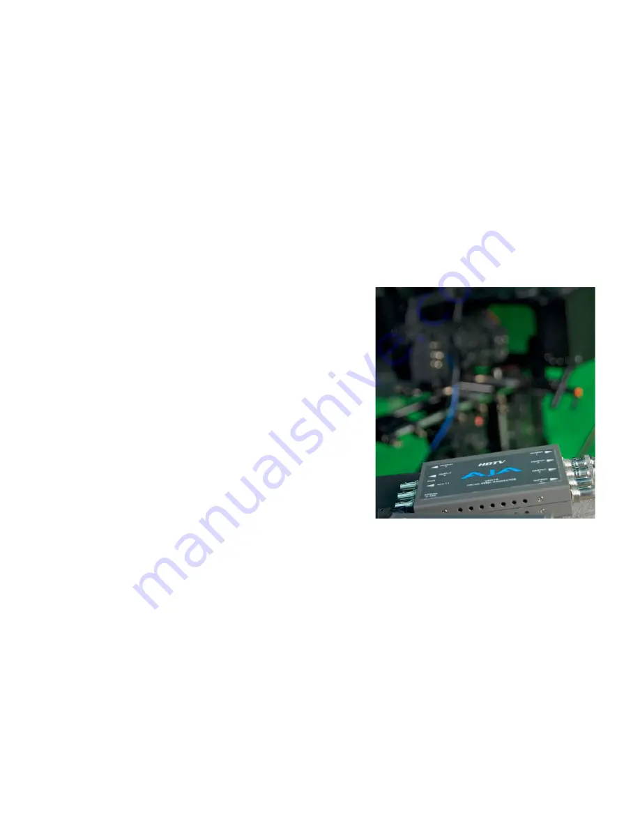
If you intend to shoot 24P then signals from a tri-level sync 

generator (like AJA’s Gen-10) will need to be input into the 

GENLOCK port on both cameras.   This is required so that 

the pulldown patterns on the two cameras sync perfectly.

With either method you should ensure that the horizontal 

and vertical phase in the genlock menu of the slave 

camera is set to 0.  There should be no need to adjust the 

phase.

OTHER MENU SETTINGS

Synchronized menu/exposure settings, record trigger and zooms using IR remote

It is easiest to set your desired gamma, matrix, and other internal settings on one camera and then 

save the scene 

fi

le to a SD card and load on the other camera.  This will ensure that both cameras 

have the same basic settings.   You can save your settings to the SD card by selecting the OTHER 

FUNCTIONS menus, TRANSFER MENU and then SAVE TO.  Select OK and press SET.  Then move the SD 

card to the other camera and select OTHER FUNCTIONS, TRANSFER MENU and LOAD FROM.  Select 

OK and press SET.

XF300/305 Whitepaper                


   Stereoscopic 3D

Tim Dashwood

11

Tri-Level Sync Generator connected 
to both cameras’ genlock terminals

Summary of Contents for XF105

Page 1: ......

Page 2: ...scopic depth It sounds simple enough but the first thing any budding stereographer should learn is some basic stereoscopic terminology These few terms may seem daunting at first but they will form the basis of your stereoscopic knowledge TERMINOLOGY Stereoscopic 3D a k a Stereo3D S 3D or S3D 3D means different things to different people In the world of visual effects it primarily refers to CGI modeli...

Page 3: ...ge Try this Hold one finger next to your ear Now stretch your other arm out straight and hold up another finger Now bring your two fingers together and touch the tips together Is was easy right Now repeat the same procedure but close one eye Were you able to touch your fingers together on the first try Now you know how important binocular vision is at close range When we look around at objects at ...

Page 4: ...rge on it creating a single image of the pen What you may not immediately perceive is that everything behind the pen appears as a double image diverged Now look at the background behind the pen and your pen will suddenly appear as two pens because your eyes are no longer converged on it This double image is retinal disparity at work and it is helping your brain determine which object is in front o...

Page 5: ...ations on our retina to create parallax separation stereoscopically recorded and displayed objects will appear to have different horizontal offsets parallax depending on their depth in the scene If an object has no perceivable amount of parallax then we consider it to appear on the screen surface just as the star in the illustration This is why converging on an object will make it appear to be at th...

Page 6: ...copic rig and it will be tweaked ever further in post production through the use of 3D mastering software Ortho stereo Hyper stereo Hypo stereo As mentioned earlier the average interocular separation of human beings is considered to be about 65mm 2 5 inches When this same distance is used as the interaxial distance between two shooting cameras then the resulting stereoscopic effect is typically kno...

Page 7: ...r parallel barrier technologies to present stereoscopic material without the use of glasses Anaglyph glasses will work with almost any display but use color filters to separate the left and right images The most common configurations are red cyan blue amber and green magenta THE QUICK MATH SOME RULES TO REMEMBER Stereoscopic Parallax Budget sometimes called Depth Budget vs Depth Bracket The Depth ...

Page 8: ...ut does the 1 30 rule apply to all scenarios No the 1 30 rule certainly does not apply to all scenarios In fact in feature film production destined for the big screen we will typically use a ratio of 1 60 1 100 or higher The 1 30 rule works well if your final display screen size is less than 65 inches wide your cameras were parallel to each other and your shots were all taken outside with the back...

Page 9: ...n ranges helicopter shots etc Side by Side Rig In order to shoot subjects in close range within 15 or 20 feet you will require a beamsplitter rig Beam splitters use a 50 50 or 60 40 mirror similar to teleprompter glass that allows one camera to shoot through the glass and then other to shoot the reflection The interaxial can be brought down to as little as 0mm 2D with beamsplitter rigs There are o...

Page 10: ...m fisheye lens adapters because the distortion will cause many geometrical disparities Shooting in the zoom range of 4 1mm to 10mm with the XF series cameras is recommended for beginners SECTION 2 SHOOTING 3D WITH PAIRS OF XF105 OR XF305 This section describes the technical intricacies of configuring a pair of XF105 or a pair of XF305 cameras with firmware v1 0 2 0 or newer to work together to cap...

Page 11: ...enlock input signal Continue to the next step for GENLOCK SYNCING the cameras TIMECODE SYNC FOR XF305 CAMERAS Connect a BNC cable from the TC terminal on one camera to the TC terminal of the other camera Set the TIMECODE MODE on both cameras to FREE RUN You can set a custom preset timecode on your designated master camera first On the master camera enter the TC UB Setup menu and then Timecode subm...

Page 12: ... Term menu to set the input to GENLOCK input signal If you intend to shoot 24P then signals from a tri level sync generator like AJA s Gen 10 will need to be input into the GENLOCK port on both cameras This is required so that the pulldown patterns on the two cameras sync perfectly With either method you should ensure that the horizontal and vertical phase in the genlock menu of the slave camera i...

Page 13: ...er camera choosing its own white balance focus or exposure Other Menu Function LCD Display Settings The following menu items refer specifically to the XF305 and some items may be located in a different sub menu in the XF105 Navigate to LCD VF SETUP CUSTOM DISPLAY OBJECT DISTANCE to ALWAYS ON Set LCD VF SETUP CUSTOM DISPLAY ZOOM POSITION to ALWAYS ON Set the OTHER FUNCTIONS CUSTOM FUNCTION OBJ DIST ...

Page 14: ...amera for each frame and therefore will be a visual disparity Using Scan Reverse function to rectify mirror image for reflected camera If you are using a beamsplitter rig you may choose to undo the flipped or flopped image in the camera that shoots the reflection from the mirror This can be done easily within the XF105 or XF305 by selecting the CUSTOM FUNCTION menu and then the SCAN REVERSE REC su...

Page 15: ...tion in a beamsplitter rig The tops of the frames must match so there is no rolling shutter disparity between the sensors If the mirror in your rig faces the ground and the upright camera mounts underneath then the camera can be mounted on the plate normally If your mirror faces up and the upright camera points down then the camera must be mounted upside down so that the top bottom orientation of ...

Page 16: ...the images of the two cameras It is best to use a left right signal muxer to see the camera images superimposed or use a professional stereoscopic monitor that can accept left and right HD SDI inputs If you have aligned your rig as closely as you can get it you can take it one step further within the camera and utilize the LENS AXIS SHIFT to tune out vertical disparity or converge on any point Jus...

Page 17: ...tailing advanced techniques for shooting posting and distributing stereoscopic 3D Remember stereoscopic 3D cinematography is a craft that can takes years to master and is a craft where even the experts are still learning new techniques As the popularity of S3D continues to rise there will by many demands on inexperienced videographers to provide stereoscopic services It is important to remember th...

Reviews: