background image

2-17

Installing the Camera

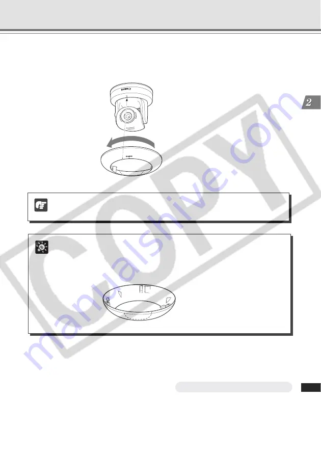
7. Attach the Ceiling Mount Cover to the camera.

Align the mark (o) on the Ceiling Mount Cover with the LED of the camera, and rotate the
cover counterclockwise to the mark (I) to secure it.

Tip

If the cables cannot be fit in the roof space, because the ceiling is concrete for example,

or they cannot be in the Ceiling Mount Cover, cut the notch of the Ceiling Mount

Cover with a plier to provide a notch to pass the cables through. In this case, attach

the Ceiling Mount Cover first, then connect the cables.

8. When you finished mounting the camera, reboot the camera to initialize the

camera position (

→ 

d

Operation Guide P.1-20).

Mounting is now complete.

Setting Up the Camera

Note

Ensure that the Ceiling Mount Cover is attached securely.

Summary of Contents for VB-C300

Page 1: ...lease read these Start Guide and Operation Guide carefully before operation Be sure to read the a Safe Use of Equipment section before using this equipment Store this manual in a readily accessible lo...

Page 2: ...ublished without consent of copyright holders if any except in such a way as permitted for personal use under relevant copyright law Notes 1 The unauthorized transfer of all or any part of the content...

Page 3: ...nterrupted The audio stream may be interrupted if you use anti virus software Disconnecting the LAN cable also disconnects audio Reconnect to the camera from the NC Viewer European Union and EEA only...

Page 4: ...C S Optional 1 9 AC Adapter PA V17 Optional 1 9 Network Video Recorder VK 64 VK 16 V1 3 Optional 1 10 Chapter 2 Installing the Camera Setup Workflow 2 2 Connect the Camera to the Network and Perform t...

Page 5: ...endix External Dimensions 3 2 VB C300 3 2 Indoor Dome Housing VB RD41S C S Optional 3 2 Specifications 3 3 I O Terminals 3 4 External Device I O Terminals 3 4 Audio I O Terminals 3 6 Video Output Term...

Page 6: ...0 Start Guide This document 11 Warranty Card NTSC model only Setup CD ROM Contents ReadMe J txt Japanese ReadMe E txt English ReadMe F txt French ReadMe G txt German ReadMe I txt Italian ReadMe S txt...

Page 7: ...of the VB C300 For detailed information about how to use the VB C300 About User s Manuals The VB C300 is provided with two documents Start Guide this manual and Operation Guide stored on the supplied...

Page 8: ...rd of your purchase to aid identification in case of theft Date of Purchase Dealer Purchased from Dealer Address Dealer Phone No Model No VB C300 Serial No a WARNING TO REDUCE THE RISK OF ELECTRIC SHO...

Page 9: ...d by turning the equipment off and on the user is encouraged to try to correct the interference by one or more of the following measures Reorient or relocate the receiving antenna Increase the separat...

Page 10: ...9 Polarization ThePA V17ACadapter optional isequippedwithapolarized2 prongplug aplug having one blade wider than the other The 2 prong polarized plug will fit into the power outlet only one way This i...

Page 11: ...ntact your nearest Canon supplier Do not continue to use the equipment as this can cause a fire or electric shock The equipment emits any smoke heat abnormal noise or unusual odor A metal object falls...

Page 12: ...a from operating correctly In this case do not limit the current for the port used by the camera Some PoE HUBs have a limit on the total current consumption of the ports and using multiple ports of a...

Page 13: ...ens will cause video defects When using the Indoor Dome Housing Optional The dome should be cleaned regularly because the video quality may get deteriorated if the surface of the dome is dirty 1 Remov...

Page 14: ...xiv...

Page 15: ...Before Using the VB C300 This chapter describes the features of the VB C300 the hardware and software requirements and the name and functions of the system components Chapter...

Page 16: ...switching function dOperation Guide P 1 10 to automatically switch between color capturing under bright conditions during daytime and monochrome capturing under dark conditions during nighttime making...

Page 17: ...gineers Up to 100 m of the LAN cable can be connected between the camera and the PoE HUB P xii Shade Correction Function NC Viewer If the background of an image is bright making the subject difficult...

Page 18: ...pplied with the VB C300 You can view the video captured by the VB C300 and control the camera Note When using the VB C300 with the VB C50 series install the Viewer for PC supplied with the VB C50 seri...

Page 19: ...r and the Viewer for PC for the VB C50 series camera Operating System Windows 2000 Professional SP4 Internet Explorer 6 0 SP1 Web Browser Windows XP SP1a Internet Explorer 6 0 SP1 Windows XP SP2 Inter...

Page 20: ...er the dialog box appears 2 Click Add The dialog box for adding Trusted sites appears If the box for Require server verification https for all sites in this zone is ticked remove the tick 3 Enter the...

Page 21: ...een rebooted or the camera is not connected to the network Continuously lights Normal operation Off When LED is set to turn OFF dOperation Guide P 1 19 Even if the LED is set to turn OFF it flashes fo...

Page 22: ...for this unit is shown here MAC address Address unique to this camera Please make a note before installing this unit P 2 8 Screw hole for tripod mounting Reset switch You can initialize settings by pr...

Page 23: ...se note that the Indoor Dome Housing VB RD41S C S is an optional product and is therefore sold separately AC Adapter PA V17 Optional This is an AC adapter dedicated to the VB C300 Use the AC adapter w...

Page 24: ...rom the network camera The VB C300 is only supported by V1 3 It is useful when using multiple network cameras Options Note The VB C300 is not supported by the older versions of VK 64 VK 16 If using an...

Page 25: ...e camera First connect the camera to the network and perform the initial setting Next install the software and view the video with the NC Viewer Finally mount the camera at the desired place Chapter P...

Page 26: ...ing the camera and the reboot Supplied Setup CD ROM 1 Connect the camera to the network and perform the initial setting Connect the camera to the PC via a HUB P 2 4 Please ask our sales person when us...

Page 27: ...e The camera may not operate as your settings depending on the capabilities of your PC and the network environment as well as factors such as the image size and quality settings of the network camera...

Page 28: ...n ON again The VB C300 is equipped with the PoE Power over Ethernet function The power can be supplied to the camera via the LAN cable from an IEEE 802 3af compliant PoE HUB When using PoE HUB Rear AC...

Page 29: ...HUB may disturb the communication Do not change connection while the camera is operating Turning the Power ON and OFF The VB C300 itself does not have a power switch If the power is supplied to the VB...

Page 30: ...e length ft 16 4 29 5 45 9 75 4 105 0 24VAC Maximum cable length m 11 18 29 46 64 Maximum cable length ft 36 1 59 0 95 1 151 0 210 0 Use a UL cable equivalent to UL 1015 as the power cable for 12VDC o...

Page 31: ...tup exe from Explorer to start the VB Initial Setup Tool Initial setting of the Camera The instructions here assumes that a single camera is connected to a PC as an example LAN cable HUB VB C300 Suppl...

Page 32: ...you do not want to specify a default gateway address disable the Enter a Default Gateway Address box Once you have entered your settings click OK Click to select Tip The factory default password is VB...

Page 33: ...nsult with your network administrator for the IP address subnet mask and default gateway address settings If 20 minutes or more have passed since the VB C300 was turned on the VB C300 stops sending re...

Page 34: ...ich asks for user name and password appears when the top page is accessed You can click Settings to set the configuration and preferences of the camera dOperation Guide P 1 2 Note For Windows Server 2...

Page 35: ...te Install the software as directed below when using the VB C300 and VB C50 series cameras together First install the VB Administration Tools supplied with the VB C50 series camera then install the VB...

Page 36: ...ect from the File menu bar to connect to the camera 1 Double click the NC Viewer icon on the desktop 2 The NC Viewer starts and displays its top menu Installing the Software and View the Camera Video...

Page 37: ...istrator account of the camera 5 Your PC is connected to the camera and the video is displayed 6 Camera connection check is complete if the video is displayed correctly Tip It is strongly recommended...

Page 38: ...ng Side View of mounting OUT IN 2 IN 1 B A 100 10BT VIDEO OUT LINE IN LINE OUT DC IN 12 13V AC IN 24V Safety Wire Ceiling Bracket LAN cable VB C300 Roof space Ceiling board Fix to an anchor or structu...

Page 39: ...ations and mark them with a pencil 100 10BT VIDE O OUT LINE IN LINE OUT DC IN 12 13V AC IN 24V B A OUT IN 2 IN 1 3 Drill two mounting screw holes and one cable hole on the ceiling Note When using the...

Page 40: ...he camera When using the AC adapter optional or external power supply connect the power cable to the camera Connect the cables to External Device I O terminals or Audio output input terminals as requi...

Page 41: ...iling is concrete for example or they cannot be in the Ceiling Mount Cover cut the notch of the Ceiling Mount Cover with a plier to provide a notch to pass the cables through In this case attach the C...

Page 42: ...Place the VB C300 at a flat and stable location VIDEO OUT LINE IN LINE OUT DC IN 12 13V AC IN 24V 100 10B T B A OUT IN 2 IN 1 Using a Tripod The screw hole for mounting a tripod is on the bottom of th...

Page 43: ...o bear the weight of the VB C300 including the In Ceiling Bracket Installation in a weak location could result in the VB C300 falling and causing serious injury At least once a year check for loosenes...

Page 44: ...eiling Note After drilling the holes clean the mounting location so that drilled refuse may not enter the inside of the dome when installing the Indoor Dome Housing 4 Mount the Backside Ceiling Bracke...

Page 45: ...l power supply connect the power cable to the camera Connect the cables to External Device I O terminals or Audio output input terminals as required to the camera DC IN 12 13V AC IN 24V 100 10BT VIDEO...

Page 46: ...ns 9 Fix the dome with a screw to prevent the dome from rotating 10 When you finished mounting the camera reboot the camera to initialize the camera position dOperation Guide P 1 20 Tip If the LED is...

Page 47: ...Appendix This appendix shows the external dimensions specifications and external device I O terminals of the VB C300 Chapter...

Page 48: ...ional 131 8mm 5 19inch 180mm 7 09inch 139 4mm 5 49inch circumscribed diameter 65 0mm 25 6inch 81 5mm 3 21inch 110mm 4 33inch 86 5mm 3 41inch 46 8mm 1 84inch 64 0mm 2 52inch 129 9mm 5 11inch 180mm 7 09...

Page 49: ...LAN x 1 RJ45 100Base TX 10Base T auto negotiation Audio IN OUT 3 5 monaural mini jack IN Connection to a microphone with amp and LINE output x 1 OUT Connection to a speaker with amp x 1 VIDEO OUT 3 5...

Page 50: ...rminals and then electrically short circuiting across the terminals ON or separating the connection OFF an interrupt can be generated for the NC Viewer I O Terminals There are External Device I O Audi...

Page 51: ...Terminal OUT The external device output terminal consists of a pair of two output terminals OUT There is no distinction between and for OUT The NC Viewer switches the 2 output terminals to disconnecte...

Page 52: ...the speaker Only the administrator can use this function Video Output Terminal For maintenance By connecting a video cable connector to this terminal you can display video image from the camera on th...

Page 53: ...3 7 Appendix...

Page 54: ...Tower 10 Metropolis Drive Hunghom Kowloon Hong Kong CANON AUSTRALIA PTY LTD 1 Thomas Holt Drive North Ryde Sydney N S W 2113 Australia CANON EUROPA N V Bovenkerkerweg 59 61 P O Box 2262 1185 XB Amste...

Reviews: