background image

3-14

SmartBase MPC200/imageCLASS MPC200
 Chapter 3: Assembly and Disassembly

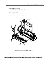
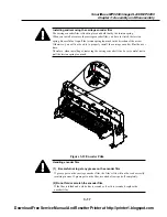
Disassembly 9.  Contact sensor drive motor

(1) Perform disassembly 8, and detach the contact sensor.

(2) Loosen the screw (a), and push the pulley toward the inside to detach the contact sensor drive belt

from the gear.

(3) Remove the screw (b), and detach the shaft stopper.
(4) Remove the 2 screws (c), and detach the grounding plate.

(5) Remove the screw (d), and detach the contact sensor drive motor together with the plate.
(6) Remove the 2 screws (e), and detach the contact sensor drive motor from the plate.

Figure 3-9 Disassembly 9

Grounding plate

Contact sensor drive belt

a

Pulley

Contact sensor drive motor

Shaft stopper

d

e

b

c

Download Free Service Manual And Resetter Printer at http://printer1.blogspot.com

Summary of Contents for SmartBase MPC200

Page 1: ...HY8 10AV 000 SEPT 2002 SmartBase MPC200 H12 2603 230V EC SmartBase MPC200 H12 2604 230V UK SmartBase MPC200 H12 2605 230V ENG GER FRN imageCLASS MPC200 H12 2608 230V AUS imageCLASS MPC200 H12 2609 23...

Page 2: ...does not apply to any countries where such provisions are inconsistent with local law Trademarks The product names and company names described in this manual are the registered trademarks of the indiv...

Page 3: ...ion to be taken to prevent damage to electronic components by electrostatic discharge If the following mark is used following the directions given Informs you of fire related cautions Informs you that...

Page 4: ...aintenance and Service This part explains how to maintain the products for adjustment and troubleshooting and service operations and service switches Chapter 5 Appendix This part explains the informat...

Page 5: ...III III REVISION HISTORY REVISION CONTENT 0 Original Download Free Service Manual And Resetter Printer at http printer1 blogspot com...

Page 6: ...CANNER MECHANISM 2 6 3 PRINTER SECTION 2 6 3 1 Overview of the Printer s Mechanical Parts 2 7 3 1 1Carriage 2 7 3 1 2 Purge section 2 7 3 1 3 Paper feed section 2 8 3 2 Paper Feed Section 2 8 3 2 1 Pa...

Page 7: ...Adjustment of the Print Head Position is Required 4 9 4 TROUBLESHOOTING 4 9 4 1 Troubleshooting Index 4 10 4 2 Errors Shown on the Display 4 10 4 2 1 User error message 4 14 4 2 2 Error codes 4 17 4...

Page 8: ...ort Output Function 4 37 7 1 1 Service report output functions 4 47 8 WIRING DIAGRAM 4 47 8 1 Wiring Diagram Chapter 5 Appendix 5 1 1 INSTALLATION 5 1 1 1 Setting up 5 1 1 2 CheckingOperations 5 2 2 U...

Page 9: ...Chapter 1 General Description Download Free Service Manual And Resetter Printer at http printer1 blogspot com...

Page 10: ...resolution full color copier With a monochrome document including half tone up to 99 pages can be copied at one time at the speed of a maximum of 14 pages minute Full Color 256 Gradation Grayscale Sc...

Page 11: ...W D H 15 59 21 57 10 87 396 mm 548 276 mm Weight 16 8 lbs 7 6 kg 2 2 Scanner Specification Type Book Sheet Effective scanning width Letter 8 42 214 mm A4 8 19 208 mm Scanning method Contact Image sen...

Page 12: ...1 Scanning Range Scanning range Sheet dimensions W L 8 5 11 7 216 mm 297 mm Thickness 0 79 20 mm Max 0 18 inch 4 5 mm Max 0 18 inch 4 5mm Max 0 16 inch 4 0 mm Max 0 16 inch 4 0 mm Letter Legal A4 Dow...

Page 13: ...emaining inside the tank Printing speed Black Approx 14 pages minute Canon standard pattern Color Approx 10 page minute Canon standard pattern Printing resolution 2400 dpi 1200 dpi Paper output tray s...

Page 14: ...W x L a 0 13 inch 3 4 mm b 0 13 inch3 4 mm c 0 12 inch 3 0 mm d 1 04 inch 26 5 mm a b c d L W Feed dirction Recmmended print area a 3 0 mm b 5 0 mm c 3 4 mm A4 4 x6 A5 B5 6 4 mm Letter Legal d 3 4 mm...

Page 15: ...400 Fixed ratio A5 A4 B5 A4 A4 B5 A4 A5 Copy mode 2 on 1 Image repeat Borderless copy Mirror image Entire image Figure 1 3 Printing Range 2 Recommended printing area Printable area Banner paper a b Ma...

Page 16: ...ard slot Compatible memory cards Compact flash Smart media Memory stick SD memory card Multimedia card Flash ATA card PCMCIA Type II Printing mode Index All frames Single frames Frame range DPOF VIVID...

Page 17: ...kup contents User data Service data Backup IC 256 kbit SRAM for control Backup device Lithium battery 3 0V DC 220 mAh Battery life Approx 5 years Service report System data list System dump list Displ...

Page 18: ...hine 1 Document cover 8 Tray extension 2 Multi purpose tra y 9 Operation panel 3 Tray extensio n 10 Platen glass 4 Eject button 11 Inner cover 5 Card slo t 12 Printhead holder 6 Indicator light 13 Pap...

Page 19: ...d keys Scrollthrough selections andincreaseor decrease the numberof copiesor the photograph file number 7 LCD Displays messages and selections and prompts during operation 8 OK key Selects or confirms...

Page 20: ...esults and to avoid printing problems Canon recommends that you only use the Canon Ink Tanks described in this guide NOTE 3 3 Consumables 3 3 1 Ink cartridge Black BCI 24 Ma de inJap an BCI 24 MadeinJ...

Page 21: ...paper sizes in portrait orientation You can use regular copier paper cotton bond paper or typical letterhead Your machine does not require special ink jet paper Legal size paper can only be used when...

Page 22: ...is delivered in the paper output tray Glossy Photo Paper GP 301 GP 301N A high gloss thick paper that produces the look and feel of a photograph Size A4 Letter Quantity 10 sheets Paper thickness lever...

Page 23: ...e each sheet as soon as it is printed Photo Paper Pro PR 101 A thick paper with a treated surface that enhances gloss and provides superior colour reproduction It is ideal for printing high quality ph...

Page 24: ...livered being careful not to touch any surfaces Do not allow transparencies to stack up in the paper output tray When your output has dried completely cover its printed side with a sheet of plain not...

Page 25: ...er to the right Paper that tends to curl is not recommended for printing photographs or graphics Use for printing mainly text Do not use print media that is in bad condition If the print media is curl...

Page 26: ...Chapter 2 Technical Reference Download Free Service Manual And Resetter Printer at http printer1 blogspot com...

Page 27: ...achine consists of the scanning assembly printing assembly and printer Figure 2 1 Mechanical Layout Pick up roller Contact sensor drive motor Paper feed motor Paper feed roller Paper eject roller Cont...

Page 28: ...ol Printer control sensor detection Power supply unit supplies power to the units and assemblies OPCNT board detects keyboard operation and displays machine information Sensor board interface with SCN...

Page 29: ...Paper edge sensor Detects the state of paper feeding and delivery Cover sensor Detects the state of inner Carriage encoder film The sensor mounted to the carriage unit reads the information from the e...

Page 30: ...200 Chapter 2 Technical Reference 2 SCANNER MECHANISM The scanner section scans documents that are to be copied Figure 2 4 Document Feed Section 1 5 4 2 3 Download Free Service Manual And Resetter Pri...

Page 31: ...he contact sensor shaft is used to keep the direction of the driving force of the contact sensor 4 Color contact sensor The color contact sensor scans the image data from the document converts it to s...

Page 32: ...nter s Mechanical Parts The printer s mechanical parts consist of the BJ cartridge carriage purge section and paper feed section Each part is explained below Figure 2 5 Printer s Mechanical Parts Carr...

Page 33: ...e BJ cartridge is not in use the nozzles are protected by a cap and the carriage is locked in place The motor s running direction controls the ink suction operation or capping wiping valve open closin...

Page 34: ...t to rotate in pickup direction As long as pickup is normal the rotating force acting on the separation roller is weaker than the friction between the recording paper and the separation roller thereby...

Page 35: ...ition printing starts on the platen 3 2 3 Paper discharge section After printing has taken place the paper is discharged by the drive of the eject roller with the sharp edged spurs forcing themselves...

Page 36: ...acement of the tank which must be replaced when the output starts to show fuzzy images or becomes blank When the ink tank has been replaced the LCD indicates a message asking if the ink tank has been...

Page 37: ...by for printing and a certain period of time elapses the print head will be capped automatically You can also cap the print head by pressing the ON OFF button to turn off the printer b Cleaning Cleani...

Page 38: ...uted while the carriage is fixed at the purge section It wipes the print head s nozzle array in a vertical motion c Cap The rubber cap protects the print head capping operation and sucks out pumping o...

Page 39: ...on 120 336 h Cleaning D All colors Bk Cl 0 24 0 28 Tank replacement after soft power ON All colors Bk Bk 0 24 Tank replacement after soft power ON Bk Cl Cl 0 28 Tank replacement after soft power ON Cl...

Page 40: ...Chapter 3 Assembly and Disassembly Download Free Service Manual And Resetter Printer at http printer1 blogspot com...

Page 41: ...nks BJ cartridge aluminium plate for BJ cartridge engine models Fixing unit and peripheral covers for LBP engines BatteryReplacement The batteries must be replaced correctly to avoid explosion Do not...

Page 42: ...led shoes favouring instead cotton clothes and rubber soled shoes Avoid working in a carpeted area Before beginning the work touch the grounded earth terminals of the main unit in order to discharge a...

Page 43: ...eaks mechanical parts should be wiped with a dampened paper towel or similar and electrical circuits wiped with tissue paper so that all ink is removed from below the IC chips If power is switched on...

Page 44: ...Turn off the printer so that the carriage locks at the home position If the BJ cartridge print head is not on the carriage the ink may dry and harden So even while transporting the printer leave the...

Page 45: ...C CARD unit Sensor board Carriage unit Platen unit Paper feed roller ASF unit Carriage motor Paper feed motor Purge unit Power supply unit 2 ASSEMBLY DISASSEMBLY 2 1 Disassembly Work Flow The work flo...

Page 46: ...detach the flat bed ass y 3 Disconnect 2 cable b 4 Remove the screw c and detach the grounding wire 5 Remove the left and right side cover Figure 3 3 Disassembly 1 Pressure plate a a c Flatbed ass y...

Page 47: ...anel 1 Perform Disassembly 1 to remove the Flat bed ass y 2 Disconnect cable b from the SPCNT board 3 Remove the 2 screws c and detach the operation panel b Operation panel a Download Free Service Man...

Page 48: ...SPCNT board Disassembly 4 PC CARD unit 1 Perform disassembly 2 and detach the Operation panel 2 Remove the 2 screws b and detach the plate 3 Remove the 4 screws c and detach the PC CARD unit a c b SP...

Page 49: ...cing the SPCNT board After replacement of the board be sure also to enter 0 as the amount of waste water in the new waste ink absorbent and adjust the print position a 3 Service reports Select service...

Page 50: ...screws a and detach the PC CARD holder 3 Remove the 4 screws b and detach the SPCNT holder 4 Remove the 4 screws c and detach the middle cover 5 Remove the paper tray unit Figure 3 6 Disassembly 5 b...

Page 51: ...3 Remove the 2 ink absorbees Disassembly 7 Power supply unit 1 Perform disassembly 6 and detach the printer unit 2 Free the 2 claws b and detach the power supply cover 3 Remove the screw c and detach...

Page 52: ...these data stored in the EEPROM on the SPCNT board Once the volume is judged to have reached 100 the message CHECK PRINTER error code 343 will be displayed and printing will stop in order to ensure th...

Page 53: ...from the contact sensor holder Handling the contact sensor Be careful not to scratch or soil the glass surface of the contact sensor Any such scratches or dirty marks may lead to image defects such as...

Page 54: ...ar 3 Remove the screw b and detach the shaft stopper 4 Remove the 2 screws c and detach the grounding plate 5 Remove the screw d and detach the contact sensor drive motor together with the plate 6 Rem...

Page 55: ...oard 3 Remove the 3 screws a and detach the sensor board Disassembly 11 ASF unit 1 Perform Disassembly 6 to remove the Printer unit 2 Remove the screw b and detach the cable guide 3 Remove the 3 screw...

Page 56: ...Push the pulley to detach the carriage belt 5 Detach the carriage encoder film from the tension spring 6 Free the claw a and detach the spur unit 7 Remove the cable guide and detach the carriage unit...

Page 57: ...eplace the encoder film Installing and removing the carriage encoder film The carriage encoder film is fixed in place and held taut by the torsion spring When you install or remove the carriage encode...

Page 58: ...isassembly 13 Purge unit 1 Perform disassembly 12 and detach the carriage unit 2 Remove the 2 screws a and detach the purge unit a Purge unit a Download Free Service Manual And Resetter Printer at htt...

Page 59: ...se soiling the blade Due to the blade s height the carriage guide shaft may touch it when the shaft is removed or installed Grease may soil the blade as a result You must not allow any grease or oily...

Page 60: ...2 Remove the 2 screws a and detach the paper feed motor Disassembly 15 Carriage motor 1 Perform disassembly 12 and detach the carriage unit 2 Remove the 2 screws b and detach the carriage motor Figure...

Page 61: ...embly 16 Disassembly 16 Platen unit 1 Perform disassembly 12 and detach the carriage unit 2 Remove the 4 springs a and detach the pressure roller unit 3 Remove the platen unit Pressure roller unit a a...

Page 62: ...bly Disassembly 17 Paper feed roller 1 Perform disassembly 16 and detach the platen unit 2 Remove the bushing a and detach the paper feed roller Figure 3 23 Disassembly 17 Paper feed roller a Download...

Page 63: ...o prevent static damage 3 Perform Disassembly 1 4 Remove the ROM from the SPCNT board using the ROM removing tool 5 Match the ROM and the IC socket in relation to the cut offs and fit the new ROM 6 Pu...

Page 64: ...Chapter 4 Maintenance and Service Download Free Service Manual And Resetter Printer at http printer1 blogspot com...

Page 65: ...d has run out BCI 24Black BCI 24Color Service Technician None 1 2 Cleaning For the cleaning procedure see this Chapter 2 HOW TO CLEAN PARTS Level Location When User Main unit outer covers When dirty D...

Page 66: ...then SRAM data is corrupted When this product is shipped after factory adjusment of the CS LED light on duration the exposure control data is stored in SRAM Because this data is preserved by the Lithi...

Page 67: ...d screwdriver Removing plastic tabs Tweezers Removing coil spring Isopropyl alcohol IPA Cleaning the cleaning location Pliers needle nose Driving retaining ring 1 7 Special Tools Tool Use Part No Grea...

Page 68: ...with a little water If the parts above are very dirty wipe with a cloth moistened with IPA isopropyl alcohol Do not use tissue paper Dust from the tissue paper causes static electricity Precautions wh...

Page 69: ...4 5 SmartBase MPC200 imageCLASS MPC200 Chapter 4 Maintenance Service Figure 4 1 Cleaning Location Platen Document glass Download Free Service Manual And Resetter Printer at http printer1 blogspot com...

Page 70: ...e SPCNT board Contact sensory ass y or lithium battery is replaced be sure to perform this adjustment Also if the color or brightness of scanned or copied images is faulty performing this adjustment m...

Page 71: ...pending on the state in which BJ cartridge is installed In order to eliminate this drift it is necessary to adjust the head position after attaching the BJ cartridge Set 2 or more sheets of normal pap...

Page 72: ...LE CHECK 7 MAINTENANCE ALIGN PRINT HEAD HORIZ PATTERN PRINTING CHANGE H VALUE A 0 CHANGE H VALUE B 0 OK OK OK OK OK Printing the horizontal line pattern REGISTRATION OK With regard to pattern B to pat...

Page 73: ...lem The paper is not fed properly The paper feed motor does not run The paper is not picked up from the auto sheet feeder The printing operation is abnormal Nothing is printed The carriage motor does...

Page 74: ...nd execute the appropriate countermeasures BLACK INK LOW Cause The ink level in the black ink tank is low Solution Replace the black ink tank CARDREADERERROR Cause There is a problem with the card slo...

Page 75: ...ution Replace carriage belt Cause Guide frame home position detection tabs is damaged or bent parts Solution Replace the damaged or bent parts Cause Carriage motor does not work Solution 1 Switch powe...

Page 76: ...l in the color ink tank is low Solutions Replace the color ink tank COVER OPEN Cause You opened the inner cover during an operation Solution Close the inner cover Cause Failure of a cover sensor Solut...

Page 77: ...is nearly full Solution If the message Check Printer has appeared replace the ink absorbent by referring to the instructions under 343 cause and action under d of 4 2 2 Error Codes in this chapter WR...

Page 78: ...ountermeasures The following item c lists all the error codes that the product can display As for the causes and countermeasures only the error codes which are newly incorporated in the unit a remedie...

Page 79: ...the notation UNQ UNIQUE Service error code No Definition 334 Printer control EEPROM check error 335 Data transmission error between the system control section and printer control section 336 BJ head a...

Page 80: ...r 7 PRINTER in service mode and the counter to 0 2 Check to make sure that no image exist in memory then turn off the power remove the appropriate parts and replace the waste ink absorber 352 Printer...

Page 81: ...etween the Operation panel unit and SPCNT board JPANEL1 2 Replace the Operation panel unit 3 Replace the SPCNT board Part of the LCD panel does not display anything 1 Check the connection between the...

Page 82: ...and SPCNT board JHEAD0 JHEAD1 6 Replace the carriage unit 7 Replace the SPCNT board The carriage motor does not run 1 Check the connection from the carriage motor to the sensor board J103 2 Check the...

Page 83: ...e Fig 4 6 3 Remove and reinstall the printhead 4 Replace the appropriate ink tank 5 Replace the printhead 6 Replace the purge unit Blotches appear Blank ink appear 1 Carry out nozzle cleaning on the p...

Page 84: ...the connection between the contact sensor and SPCNT board JCS1 3 Replace the contact sensor unit 4 Replace the SPCNT board The halftone image contains black dots 1 Clean the Document glass 2 Check the...

Page 85: ...the operation panel unit 3 Replace the SPCNT board The key on the operation panel fails to work properly 1 Check the connection between the operation panel unit and the SPCNT board JPANEL1 2 Replace...

Page 86: ...tings These setting items are for functions required during installation such as NL equalizer and transmission levels 3 NUMERIC Param NUMERIC parameter settings These setting items are for inputting n...

Page 87: ...can be registered set by the following operations Figure 4 7 Service Data Setting Method 3 Menu itemselection Select themenu item by pressing the or button 100 LTR TEXT PLAIN 01 Standbay Copy mode 1...

Page 88: ...hange these settings 5 2 3 Service data setting 1 SSSW Bit Service data Error managemaent Not used Not used Service soft switch setting 7 6 5 4 3 2 1 0 SW01 SW50 1 0 Scan Photo print SW02 to 50 Not us...

Page 89: ...d 86 SUCTION 2 Numeric Param 3 PRINTER COUNT Printer section reset function Waste ink capacity entry Print counter Yes No 4 PRINTER RESET 5 INK ABS CAPA Scan Photo Print Download Free Service Manual A...

Page 90: ...ion Total number of pages printed scanned All user data service data activity management data and image data initilization except COUNTER Data initialization mode settings ROM management Version No an...

Page 91: ...ce data a SSSW Service Soft Switch settings The items registered and set by each of these switches comprise 8 bit switches The figure below shows which numbers are assigned to which bits Each bit has...

Page 92: ...This allows the waste ink capacity for the ink absorbed during cleaning to be checked or entered When entering the waste ink capacity use the button to enter a value 0 to 100 The amount of waste ink c...

Page 93: ...e head cleaning If the symptom is not solved even after the cleaning is done three times do the head refreshing If the head refreshing does not solve the symptom replace the BJ cartridge or the ink ca...

Page 94: ...and then ON OFF button 6 2 1 Test mode overview Test mode can be executed by following the menu items from the display a DRAM tests Writes data to DRAM image storage areas and reads that data to check...

Page 95: ...x 2 Not used 3 SENSOR 4 Not used 5 Not used 6 Not used 7 PANEL 8 FB 333pps B W 9 LINE DETECT 3 DISP LEDTIME 4 REG LEDTIME 5 SHADING TEST 6 FB READ 2 CS 3 PRINT 4 MODEM NCU 5 AGING TEST 6 FACULTY TEST...

Page 96: ...cates an address for which read testing is complete Error Error display Error display Normal end Complete no error Complete error WRT 33CC RD 3333 ADR 2800 Restart by pressing Start key WRT data writt...

Page 97: ...re operating correctly a Sensor tests The sensor test is selected by pressing the button from the faculty test menu In this test you can check the status of each sensor of this fax in item 1 on the di...

Page 98: ...and press the set button DS of DES of DOC A4 DS Document sensor DES Document edge sensor on of document no document DOC Document wide sensor A4 DS DES and DOC these sensors are not in this machine CVR...

Page 99: ...this operation b 2 LED lamp test The LED lamp test is selected by pressing the Start button after the display test When the Start button is pressed all the lamps on the control panel light Check for a...

Page 100: ...tart button Press the Start button Press the start button Press the start button H pattern display All LCD dots display _ Pattern display All LED lamps light up When a button is pressed the correspond...

Page 101: ...ons history reports a List of service reports The fax outputs the service reports shown below Reporttype Operations 1 System data list In the service mode and select SERVICE REPORTS using the button P...

Page 102: ...ter 4 Maintenance Service a 1 System data list This list shows service data 1 5 7 9 setting statuses The following is a sample list Figure 4 18 System Data List 1 7 Download Free Service Manual And Re...

Page 103: ...4 39 SmartBase MPC200 imageCLASS MPC200 Chapter 4 Maintenance Service Figure 4 19 System Data List 2 7 Download Free Service Manual And Resetter Printer at http printer1 blogspot com...

Page 104: ...4 40 SmartBase MPC200 imageCLASS MPC200 Chapter 4 Maintenance Service Figure 4 20 System Data List 3 7 Download Free Service Manual And Resetter Printer at http printer1 blogspot com...

Page 105: ...4 41 SmartBase MPC200 imageCLASS MPC200 Chapter 4 Maintenance Service Figure 4 21 System Data List 4 7 Download Free Service Manual And Resetter Printer at http printer1 blogspot com...

Page 106: ...4 42 SmartBase MPC200 imageCLASS MPC200 Chapter 4 Maintenance Service Figure 4 22 System Data List 5 7 Download Free Service Manual And Resetter Printer at http printer1 blogspot com...

Page 107: ...S MPC200 Chapter 4 Maintenance Service Figure 4 23 System Data List 6 7 Download Free Service Manual And Resetter Printer at http printer1 blogspot com Download Free Service Manual And Resetter Printe...

Page 108: ...S MPC200 Chapter 4 Maintenance Service Figure 4 24 System Data List 7 7 Download Free Service Manual And Resetter Printer at http printer1 blogspot com Download Free Service Manual And Resetter Printe...

Page 109: ...nance Service a 2 System dump list This list shows the past communications statuses and error communications history The following is a sample list Figure 4 25 System Dump List Download Free Service M...

Page 110: ...G JPEG Not used G3 ECM Not used PRINT READ Total number df pages printed scanned Display example PRINT 30 100 READ 30 100 Indicates the value input with Service Data 8 CLEAR COUNTER Indicates the valu...

Page 111: ...CNT board Power supply unit Carriage unit 1 7 4 1 JPSU1 JRMTR1 3 1 J102 1 4 J105 1 2 J103 4 1 J104 1 27 1 27 JHEAD0 JHEAD1 1 22 JEXT1 22 1 J101 PS2 PS1 Paper edge sensor Pick up sensor Contact sensor...

Page 112: ...Chapter 5 Appendix Download Free Service Manual And Resetter Printer at http printer1 blogspot com...

Page 113: ...he machine Loading Paper Set paper in the auto sheet feeder in PAPER SIZE under PAPER SELECT set the size of paper that is to be used 1 2 Checking Operations Copy operation Make a copy and check that...

Page 114: ...press the menu buttom 1 ENLARGE REDUCE 2 PAPER SELECT 3 DENSITY 4 IMAGE QUALTY 9LEVL LIGHT DARK PRESET RAITO ZOOM FIT TO PAGE 400 MAX 141 A5 A4 115 B5 A4 100 86 A4 B5 70 A4 A5 25 MIN A4 LTR B5 A5 4 6...

Page 115: ...R IMAGE ENTIRE IMAGE VERTICAL HORIZONTAL AUTO MANUAL 4 3 2 1 4 3 2 1 SIZE TYPE LTR 4 6 A4 PHOTO GLOSSY H RES Download Free Service Manual And Resetter Printer at http printer1 blogspot com Download Fr...

Page 116: ...FRESHING ALIGN PRINT HEAD ROLLER CLEANING LOW INK WARNING INK COUNT RESET QUIET MODE EXTENSHION AMOUNT CARD PROTECT DISPLAY LANGUAGE ON OFF ON OFF SMALL LARGE ON OFF ENGLISH FRENCH SPANISH GERMAN ITAL...

Page 117: ...TA NOZZLE CHECK HARD CLEANING HEAD REFRESHING ALIGN PRINT HEAD ROLLER CLEANING LOW INK WARNING INK COUNT RESET QUIET MODE EXTENSION AMOUNT CARD PROTECT DISPLAY LANGUAGE ON OFF ON OFF SMALL LARGE ON OF...

Page 118: ...AMS SINGLE FREAM SELECT PAPER SIZE SELECT PAPER TYPE LTR 4 6 A4 PHOTO PAPER PRO PLAIN PAPER LTR 4 6 A4 PHOTO PAPER PRO PLAIN PAPER LTR 4 6 A4 PHOTO PAPER PRO PLAIN PAPER SELECT PAPER SIZE FILE NO 1 to...

Page 119: ...PER SIZE SELECT PAPER TYPE BORDERLESS PRINT ON OFF SELECT PAPER SIZE SERECT PAPER TYPE BORDERLESS PRINT ON OFF 2 VIVID PHOT PRINT ON OFF 3 PHOTO PRINT DATE LTR 4 6 A4 PHOTO PAPER PRO PLAIN PAPER LTR 4...

Page 120: ...NING LOW INK WARNING INK COUNT RESET QUIET MODE EXTENSION AMOUNT CARD PROTECT DISPLAY LANGUAGE ON OFF ON OFF SMALL LARGE ON OFF ENGLISH FRENCH SPANISH GERMAN ITALIAN DUTCH FINISH PORTUGUESE NORWEGIAN...

Page 121: ...Download Free Service Manual And Resetter Printer at http printer1 blogspot com...

Page 122: ...0902 IP CANON INC Download Free Service Manual And Resetter Printer at http printer1 blogspot com Download Free Service Manual And Resetter Printer at http printer1 blogspot com...

Reviews: