7
AUDIO
OUT
VIDEO
S VIDEO
RGB
R
G
OUT
EXIT
AC INLET
AC OUTLET
75
Ω
OFF
ON
24/96
100/60
ID 0
ID 1
RS-232C
SYNC OFF
ON
IN
B
R
L
SYNC
1
0
75
Ω
OFF
ON
SYNC OFF
ON
24/96
100/60
ID 0
ID 1
1
0
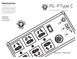
Rear Panel
AUDIO OUT terminals (stereo)
VIDEO OUT terminal
S-VIDEO OUT terminal
RGB OUT terminals
External synchronization input terminal
(See page 19)
RS-232C terminal
AC outlet
AC inlet
AUDIO IN terminals (stereo)
VIDEO IN terminal
S-VIDEO IN terminal
Communication speed selector
Electronic shutter speed selector
Set this switch for communication with a
computer. (Left: 2400 bps, right: 9600 bps).
Set this switch when the screen flickers
(Left: 1/100 sec, right: 1/60 sec).
If the screen flickers, change the setting of this selector.
Screen flicker is caused mainly by fluorescent lamps and
tends to occur in the areas where power frequency is 50
Hz. Factory default is set to 1/60.
• In areas where the power frequency is 50 Hz, set it to
1/100.
• In areas where the power frequency is 60 Hz, set it to
1/60.
See page 16 for system construction.
Use this terminal when controling the RE-350
by a computer (see page 16, 20).
Should not exceed 5A. This outlet is not
interlocked.
Terminator selection switch
Set this switch to ON when external
synchronization signal must be
terminated (see page 19).
SYNC selection switch
Set this switch to ON to add synchronization
signal to G signal when using an RGB monitor
(see page 16). When the switch is set to OFF,
synchronization signal will be output to the
SYNC terminal of the RGB OUT terminals.
ID number
setting switch
Set this switch when
controlling the RE-
350 by a computer.
MEMO
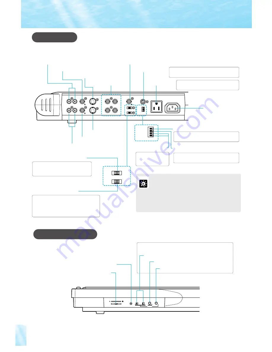
Right Side Panel
MIC
1
2
3
4
SC
PHASE
H
MIC LEVEL
Microphone volume control knob
MIC IN jack
(see page 17)
Use to adjust external synchronization (see page 19).
Hue fine-adjustment volume
Hue
(sub carrier)
selector
Horizontal phase adjustment volume