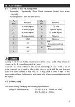


7
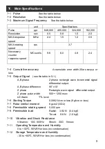
4-5
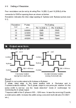
Setting of Resolution
Four resolutions can be set by shorting Pins 14 (SEL1) and 15 (SEL2) of the
connector to GND or opening them as shown at below.
Resolution indicates the inter-edge spacing of A-phase and B-phase pulses (see
5-1).
5.
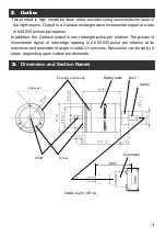
Output wave form
5-1
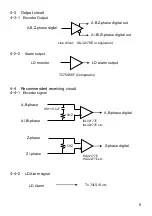
Encoder signal output
【Note】
Z phase is not synchronized with A phase or B phase
Z phase rising edge
is the same position both in Clockwise and in
Counterclockwise rotation.
The Z-phase output is one pulse per rotation. As the
pulse width is narrow, use the "peak detection" mode of oscilloscope for
monitoring the Z-phase signal.
The pulse width of the Z-phase is 500 – 1250 nsec. In case the receiving IC needs
a wider pulse width, increase the width using a one-shot multi-vibrator (74 LS221
etc.).
Resolution
(sec)
Pulses
ppr
Pin Setting
Pin 14 (SEL1)
Pin 15 (SEL2)
0.5
648,000
GND
GND
1.0
324,000
Open
GND
2.0
162,000
GND
Open
0.8
405,000
Open
Open
5
5
5
5 .
.
.
.
Output wave form
A-phase
B-phase
Z-phase
A-phase
B-phase
500~1250nsec
90°±10°
Clockwise rotation
l
ooking from shaft side.
Counterclockwise rotation
l
ooking from shaft side.
Z-phase
90°±10°
500~1250nsec


