


Chapter 3
3-11
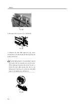
F-3-38
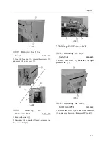
3) Remove the three screws [1], and remove the
sensor mount (upper) [2]. Then, remove the connector
[3] on the photosensor PCB.
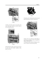
F-3-39
4) Disconnect the connector [1] and remove the screw
[2], and remove the horizontal registration home
position sensor [3].
F-3-40
5) Turn the gear [1] in the direction of the arrow, and
move the punch unit section [2] to the far side.
F-3-41
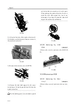
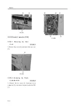
6) Remove the tie wrap with lock [1] while holding its
claw between your fingers. (The tie wrap must be
removed without being cut.)
7) Disconnect the three connectors [2] and remove the
screw [3], and remove the harness guide [4].
[2]
[1]
[3]
Summary of Contents for Puncher Unit-L1
Page 1: ...Feb 21 2005 Service Manual Finisher Sorter DeliveryTray Puncher Unit P1 ...
Page 2: ......
Page 6: ......
Page 10: ......
Page 11: ...Chapter 1 Specifications ...
Page 12: ......
Page 14: ......
Page 19: ...Chapter 2 Functions ...
Page 20: ......
Page 22: ......
Page 34: ......
Page 35: ...Chapter 3 Parts Replacement Procedure ...
Page 36: ......
Page 53: ...Chapter 4 Maintenance ...
Page 54: ......
Page 56: ......
Page 76: ...4 Mount the rear cover to the Puncher 5 Turn on the power of the host machine ...
Page 78: ......
Page 79: ...Chapter 5 Error Code ...
Page 80: ......
Page 82: ......
Page 87: ...Chapter 5 5 5 5 3 5 E592 0003 8767 ...
Page 88: ...T 5 7 ...
Page 91: ...Feb 21 2005 ...
Page 92: ......


