


Chapter 3
3-4
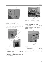
3.2.3.3
Removing the Right
Guide Unit
0003-6799
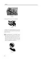
1) Remove four screws [1], and remove the right
guide assembly [2].
F-3-12
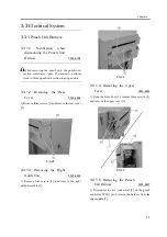
3.2.3.4
Removing the Upper
Cover
0003-6801
1) Open the front door [1], remove three screws [2],
and remove the upper cover [3].
F-3-13
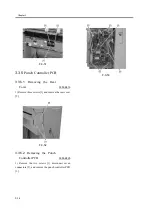
3.2.3.5
Removing the Punch
Unit
0003-6802
1) Remove E-ring [1], washer [2], and puncher spring
[3].
F-3-14
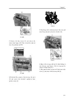
2) Turn the gear [1] in the direction of the arrow, and
move the punch unit section [2] to the front side.
F-3-15
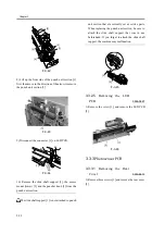
3) Remove the three screws [1], and remove the
sensor mount (upper) [2]. Then, remove the connector
[3] on the photosensor PCB.
Summary of Contents for Puncher Unit-L1
Page 1: ...Feb 21 2005 Service Manual Finisher Sorter DeliveryTray Puncher Unit P1 ...
Page 2: ......
Page 6: ......
Page 10: ......
Page 11: ...Chapter 1 Specifications ...
Page 12: ......
Page 14: ......
Page 19: ...Chapter 2 Functions ...
Page 20: ......
Page 22: ......
Page 34: ......
Page 35: ...Chapter 3 Parts Replacement Procedure ...
Page 36: ......
Page 53: ...Chapter 4 Maintenance ...
Page 54: ......
Page 56: ......
Page 76: ...4 Mount the rear cover to the Puncher 5 Turn on the power of the host machine ...
Page 78: ......
Page 79: ...Chapter 5 Error Code ...
Page 80: ......
Page 82: ......
Page 87: ...Chapter 5 5 5 5 3 5 E592 0003 8767 ...
Page 88: ...T 5 7 ...
Page 91: ...Feb 21 2005 ...
Page 92: ......


