<Button and LCD test>
Confirm the operation after replacement of the operation panel unit, board, or LCD unit.
1) In the button and LCD test mode, press the Stop/Reset button. The LCD turns blue, waiting for a button to be pressed.
2) Press each button of the operation panel.
3) Only one button should be pressed at one time. If 2 or more buttons are pressed at the same time, only one of them is considered to
be pressed, and the other buttons are ignored.
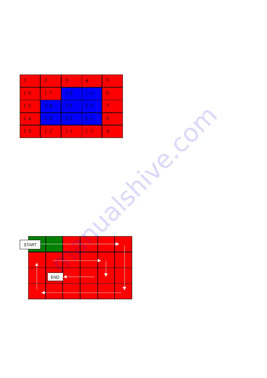
The LCD is divided into 25 segments, representing each button. The color of a segment corresponding to the pressed button
changes to red.
After all the 17 buttons are pressed, the remaining segments (from 18 to 25) turn red at the same time.
4) Rotate the Easy-Scroll Wheel clockwise and counterclockwise 1 round (24 steps) each, as follows:
4-1) Rotate the Easy-Scroll Wheel clockwise step by step. The LCD is divided into 24 segments, representing each step. The color
of a segment corresponding to the step changes from red to green.
If the wheel is rotated counterclockwise before clockwise round completes, the color of segment(s) corresponding to the
number of steps the wheel is rotated counterclockwise returns to red.
If the wheel keeps rotated clockwise over 1 round (24 steps), the color of segment(s) corresponding to the extra number of
steps returns to red, starting with the "Start" segment in the figure below.
4-2) When the Easy-Scroll Wheel is rotated clockwise 1 round (24 steps), press the OK button.
4-3) Rotate the Easy-Scroll Wheel counterclockwise step by step. The LCD is divided into 24 segments, representing each step.
The color of a segment corresponding to the step changes from green to blue.
If the wheel is rotated clockwise before counterclockwise round completes, the color of segment(s) corresponding to the
number of steps the wheel is rotated clockwise returns to green.
If the wheel keeps rotated counterclockwise over 1 round (24 steps), the color of segment(s) corresponding to the extra
number of steps returns to green, starting with the "Start" segment in the figure below.
1.
ON/OFF button
2.
Paper Feed Switch button
3.
NAVI button
4.
HOME button
5.
Back button
6.
Up cursor button
7.
Right cursor button
8.
Down cursor button
9.
Left cursor button
10.
Left function button
11.
Right function button
12.
OK button
13.
[+] button
14.
[-] button
15.
Black button
16.
Color button
17.
Stop/Reset button
40 / 45
Summary of Contents for PIXMA MP970
Page 30: ...28 45 ...
Page 40: ...Left margin correction flowchart 38 45 ...
Page 41: ...39 45 ...
Page 46: ... 2 Ink absorber counter value print Print sample 3 4 Verification Items 44 45 ...
Page 55: ...B PARTS LAYOUT PARTS LIST FIGURE 1 PACKING CONTENTS PRINT HEAD B 1 ...
Page 57: ...FIGURE 2 AC ADAPTER B 3 ...
Page 59: ...FIGURE 3 EXTERNAL COVERS SCANNER UNIT B 5 ...
Page 61: ...FIGURE 4 DOCUMENT PRESSURE PLATE UNIT B 7 ...
Page 63: ...FIGURE 5 OPRATION PANEL UNIT B 9 ...
Page 65: ...FIGURE 6 MAIN CASE UNIT FRONT DOOR UNIT B 11 ...
Page 67: ...FIGURE 7 CARD BOARD ASS Y IrDA BOARD ASS Y B 13 ...
Page 69: ...FIGURE 8 LOGIC BOARD ASS Y B 15 ...
Page 71: ...FIGURE 9 BOTTOM CASE UNIT INK ABSORBER KIT B 17 ...
Page 73: ...FIGURE 10 SHEET FEEDER UNIT B 19 ...
Page 75: ...FIGURE 11 CARRIAGE UNIT B 21 ...
Page 77: ...FIGURE 12 PLATEN UNIT B 23 ...
Page 79: ...FIGURE 13 PURGE UNIT B 25 ...
Page 81: ...FIGURE 14 PAPER FEED CARRIAGE LIFT PART B 27 ...
Page 83: ...C OPTION CONSUMABLES FIGURE 15 OPTION CONSUMABLES C 1 ...
Page 86: ...E TOOL FIGURE 16 TOOL E 1 ...


