Canon PIXMA MP950 Service Manual Download Page 10

2.  LIST OF ERROR DISPLAY / INDICATION


Errors and warnings are displayed on the LCD.


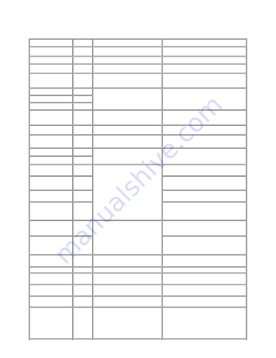
2-1.  Operator Call Errors (by Alarm LED Blinking in Orange)


Error


Error code


Message on the LCD


Solution

No paper (ASF). 


[1000]


Auto sheet feeder.


There is no paper. Load paper and press [OK].


Set the paper in the ASF, and press the OK button.

No CD / DVD tray.

*1


[1001]


There is no CD-R tray. Attach the tray and press [OK].


Set the CD / DVD tray, and press the OK button.


No paper in the front paper feed 
cassette. 


[1003]


Cassette.


There is no paper. Load paper and press [OK].


Set the paper in the cassette, and press the OK button.

No CD or DVD

*1


[1002]


Printable disc is not set. Correctly place a disc in the CD-R 
tray and press [OK].


Set a CD or DVD in the CD / DVD tray (which is ejected at error 

occurrence), and inset the CD / DVD tray in the proper position. Then, 
press the OK button. 


Paper jam. 


[1300]


The paper is jammed. Clear the paper and press [OK].


Remove the jammed paper, and press the OK button.

Paper jam in the rear guide. 


[1303]


Paper jam in the under guide. 


[1304]


No ink. 


[1600]


Ink has run out. Replace the ink tank and close the cover.
(U041)


Replace the empty ink tank(s) and close the cover. When pressing the 
OK button, printing can be continued though ink may run out during 
printing..

Ink tank not installed. 


[1660]


The following ink tank cannot be recognized. Applicable 
ink color (U043)


Install the applicable ink tank(s) properly, and confirm that the LED's of 
all the ink tanks light red.

The print head is not installed or it 
is not properly installed.


[1401]


Print head is not installed. Install the print head.


Install the print head properly.


The print head temperature sensor 
error 


[1403] 


Error code


Handle this error by turning ON/OFF the machine. If not recovered, the 
print head may have problems. Replace the print head.


Faulty EEPROM data of the print 
head 


[1405]


Inner cover open before printing on 
paper.


(print 
continuable). 
[1841]

*2


Inner cover is open. Close the inner cover and press [OK].


Close the inner cover, and press the OK button.

Inner cover open during printing on 
paper. 


(print NOT 
continuable). 
[1846]

*2


Close the inner cover, and press the OK button to clear the error. The 
paper being printed at error occurrence will be ejected without printing 
the remaining data for the ejected paper, then printing will resume from 
the next page.

Inner cover open during printing on 
paper (print continuable). 


(print 
continuable). 
[1851]

*1


Close the inner cover, and press the OK button.

Inner cover open during printing on 
paper 


(print NOT 
continuable). 
[1856]

*1


Close the inner cover, and press the OK button to clear the error. The 
paper being printed at error occurrence will be ejected without printing 
the remaining data for the ejected paper, then printing will resume from 
the next page.

Inner cover closed during CD / 
DVD printing 


(print 
continuable). 
[1850]

*1


Open the inner cover, place the CD-R tray and press [OK]. Open the inner cover which functions as the CD / DVD tray feeder, set 

the CD / DVD tray in the feeder, and press the OK button.

Inner cover closed during CD / 
DVD printing 


(print NOT 
continuable). 
[1855]

*1


Open the inner cover, and press the OK button to clear the error. The 
CD or DVD being printed at error occurrence will be ejected without 
printing the remaining data for the ejected CD or DVD, then the next 
print job will be done.


Multiple ink tanks of the same color 
installed. 


[1681]


More than one ink tank of the following color is installed. 
(U075)


Replace the wrong ink tank(s) with the correct one(s).

Ink tank in a wrong position. 


[1680]


Some ink tanks are not installed in place. (U072)


Install the ink tank(s) in the correct position.

Warning:  The waste ink absorber 
becomes almost full. 


[1700]


The waste ink absorber is almost full. Press [OK] to 
continue but early replacement recommended. <See 
manual>


Press the OK button. The waste ink absorber full error (service call 
error) may occur soon.

The connected digital camera or 
digital video camera does not 
support Camera Direct Printing. 


[2001]


Incompatible device detected. Remove the device.


Remove the cable between the camera and the machine.

Automatic duplex printing cannot 
be performed. 


[1310]


This paper is not compatible with duplex printing. Remove 
the paper and press [OK].


Press the OK button to eject the paper being used at error occurrence. 
Printing will resume from on the front side of the next page. Te data of 
the back of the page in printing when the error occurred  is not printed.

Failed in automatic print head 
alignment. 


[2500]


Auto head align has failed. Press [OK] and repeat 
operation. <See manual>


Press the OK button.


- If paper is being fed at error occurrence, the error is indicated after the 

paper is ejected.


- If the error occurs, the print head alignment values are not changed.


- After exit from the error by the OK button, the automatic print head 

alignment will not be re-done.


When printing was not possible due to no ink or no ink ejection.


or, the AD value of the sensor was incorrect.


1-5

Summary of Contents for PIXMA MP950

Page 1: ...ght 2005 Canon U S A This technical publication is the proprietary and confidential information of Canon U S A which shall be retained for reference purposes by Authorized Service Facilities of Canon U S A Its unauthorized use is prohibited ...

Page 2: ...ks or trademarks of the respective holders Copyright All rights reserved No parts of this manual may be reproduced in any form or by any means or translated into another language without the written permission of Canon Inc except in the case of internal business use Copyright 2005 by Canon Inc CANON INC Inkjet Device Quality Assurance Div 2 451 Tsukagoshi 3 chome Saiwai ku Kawasaki shi Kanagawa 21...

Page 3: ...ubleshooting of the PIXMA MP950 Part 2 Technical Reference New technology and technical information such as FAQ s Frequently Asked Questions of the PIXMA MP950 Part 3 Appendix Block diagrams and pin layouts of the PIXMA MP950 Reference This manual does not provide sufficient information for disassembly and reassembly procedures Refer to the graphics in the separate Parts Catalog ...

Page 4: ... 4 White sponge sheet attachment 5 Solenoid position 6 Front door damper position 7 User mode 8 Service mode Service mode operation Destination settings Button and LCD test Waste ink amount setting 3 4 Verification Items 1 Service test print 2 EEPROM information print 4 MACHINE TRANSPORTATION Part 2 TECHNICAL REFERENCE 1 NEW TECHNOLOGIES 2 CLEANING MODE AND AMOUNT OF INK PURGED 3 PRINT MODE 3 1 No...

Page 5: ...Part 1 MAINTENANCE ...

Page 6: ... replacement At waste ink absorber replacement To reset the waste ink counter None Perform in the service mode 1 min Waste ink amount settings EEPROM settings At logic board replacement At waste ink absorber replacement To set the waste ink amount to the waste ink counter None Perform in the service mode 1 min Paper feed motor position adjustment At paper feed motor replacement To adjust the belt ...

Page 7: ...per feed roller cleaning When paper does not feed properly To clean the paper feed rollers Machine buttons 2 min CD DVD print position adjustment 1 At CD DVD printing when necessary To correct CD DVD print position Computer application software 5 min Bottom plate cleaning When the back side of the paper is smeared To clean the platen ribs Plain paper Computer settings via the MP driver 1 min Scann...

Page 8: ...h the default settings in the Windows XP driver using Photoshop 7 0 Photo chart When printing the Canon standard pattern on 4 x 6 Photo Paper Plus Glossy in borderless printing with the default settings in the Windows XP driver using Windows XP Photo Printing Wizard The print yield in the table above is an average value measured in continuous printing using the ink tank immediately after it is uns...

Page 9: ...To the table of contents To the top Part 1 1 MAINTENANCE 1 4 ...

Page 10: ...tinuable print continuable 1851 1 Close the inner cover and press the OK button Inner cover open during printing on paper print NOT continuable 1856 1 Close the inner cover and press the OK button to clear the error The paper being printed at error occurrence will be ejected without printing the remaining data for the ejected paper then printing will resume from the next page Inner cover closed du...

Page 11: ...te ink absorber full 5B00 The waste ink absorber is full Ink absorber kit 8 times Print head temperature rise error 5200 The print head temperature exceeded the specified value Print head Logic board ass y 9 times EEPROM error 6800 A problem occurred in writing to the EEPROM Logic board ass y 11 times Carriage lift mechanism error 5110 The carriage did not move up or down properly PR lift shaft as...

Page 12: ... the error occurrence Settings cannot be changed when printing stickers With Sticker print selected the Settings button was pressed The error message is displayed for a while then the LCD automatically returns to the display before the error occurrence Change the setting after removing the card With a memory card inserted in the slot change of the Read Write attribute was attempted The error messa...

Page 13: ...ies to display the menu or sub menu the message is displayed Select Yes and press the OK button The image selection is cancelled and the menu or sub menu is displayed Select No and press the OK button The LCD returns to the display immediately before the message was displayed Symptom Solution Faulty operation The power does not turn on The power turns off immediately after power on Confirm the con...

Page 14: ...aning Clean the paper path with cotton swab or cloth Clean the ASF sub rollers A part of a line is missing on printouts Replace the ink tank or print head 1 Color hue is incorrect Replace the ink tank or print head 1 Perform print head alignment Printing is incorrect Replace the logic board ass y No ejection of black ink Replace the ink tank or print head 1 Remove foreign material from the purge u...

Page 15: ...To the table of contents To the top Part 1 2 LIST OF ERROR DISPLAY INDICATION 1 10 ...

Page 16: ... counter See 3 3 Adjustment Settings 8 Service mode Service test print EEPROM information print Carriage unit QM2 3065 At replacement 1 Apply grease to the sliding portions See 3 3 Adjustment Settings 2 Grease application After replacement 1 Correct the CD DVD and automatic print head alignment sensors See 3 3 Adjustment Settings 8 Service mode 2 Check the ink system function See 3 3 Adjustment Se...

Page 17: ...th ink Protect the housing from scratches Exercise caution with the red screws as follows i The red screws of the paper feed motor may be loosened only at replacement of the paper feed motor unit DO NOT loosen them in other cases ii DO NOT loosen the red screws on both sides of the main chassis securing the carriage shaft positioning they are not adjustable in servicing Timing slit strip film QC1 ...

Page 18: ... Remove the four screws from the back Then remove one screw from the upper left and one from the upper right and detach the side cover from the main case III Remove the front cover L and the side cover L Front cover L Be cautious not to contact the release lever to avoid a scratch or breaking claws After removing the front cover release the claws of the side cover and detach it from the main case ...

Page 19: ...ch the main case plate R After detaching the main case plate R the photo in the left by removing one screw remove the cable cover the photo in the right by sliding the side cover R outward Remove the side cover R Be cautious not to contact with the LED Windows indicated in green card board area For the location of the claws on the side cover R the main case and the bottom case see the photos below...

Page 20: ...disconnecting the cable The right photo after disconnecting the cable See 3 2 Connector Location and Pin Layout VI Remove the scanner stop arm While holding the scanner unit disengage the scanner stop arm from the main case unit Disengage the scanner stop arm from the scanner unit by slightly twisting the scanner stop arm 1 15 ...

Page 21: ... unit Lift the FAU out from the hinge holes of the scanner unit By pulling both sides of the main unit slightly outward detach the scanner unit from one side then the other VIII Remove the paper support Disengage one side of the paper support from the main case then the other side The photo on the right ahows the main case unit with the external parts removed 1 16 ...

Page 22: ...o release the four claws under the hinge For the claws locations see the photo in the left which shows the back side of the panel indicated by the red circles For the hole locations on the panel see the photo in the right The green circles shows the holes which are usually covered by the LCD monitor II Remove the panel board Remove three screws Detach the panel board from the FAU top cover Take no...

Page 23: ... FAU completely III Remove the LCD top cover Peel off the black stickers blind sheets indicated by the red circles from the lower part of the LCD monitor and remove two screws Remove the LCD top cover by raising its foot The LCD front cover can be removed with the operation panel and the panel board attached 1 18 ...

Page 24: ... to ignition or emission of smoke For details on wiring see Parts Catalog and See 3 2 Connector Location and Pin Layout Rear view after removing the main case I left side AC adapter PF motor II right side LogicBoard I Logic board ass y wiring Status in which each cable is bundled in the right side of the bottom case unit Be cautious of the points in the red circles 1 19 ...

Page 25: ... the bottom case unit are removed II Wiring at the side of the AC adapter and the paper feed morter Status in which the bottom case unit and the AC adapter are attached Be cautious of the position of the solenoid relay harness connector in the red circle 1 20 ...

Page 26: ... Status in which the bottom case unit and the AC adapter are removed To the table of contents To the top Part 1 3 REPAIR 3 2 1 21 ...

Page 27: ... indicated by the blue arrow in the figure below 2 After replacement be sure to perform the service test print and confirm that no strange noise or faulty print operation due to dislocation of the belt or gear or out of phase motor etc occurs Note The red screws securing the paper feed motor may be loosened only at replacement of the paper feed motor unit DO NOT loosen them in other cases 2 Grease...

Page 28: ...2 CL base CL gear 3 PR shaft LF roller bushing To the table of contents To the top Part 1 3 REPAIR 3 3 1 to 2 1 23 ...

Page 29: ...ines cross in the photo below Peel off the cover sheet from the double sided adhesive tape and slowly close the document cover with the sponge frame on The sponge sheet will attach to the sponge frame Open the document cover to confirm the following No extension of the sponge edges over the mold part of the document cover No gap between the platen glass reference edges and the corresponding sponge...

Page 30: ...e check pattern Deep cleaning To improve the print head nozzle conditions when the cleaning is not effective Since the deep cleaning consumes more ink than the cleaning use this function only when necessary Auto head align automatic print head alignment To improve unsatisfactory print results or dot misalignment on a line Manual head align manual print head alignment To improve unsatisfactory prin...

Page 31: ...ent Settings 8 Service mode Destination settings procedures 6 times Green COPY Print head deep cleaning Cleaning of both black and color 7 times Orange Alarm LF correction Not used for MP950 8 times Green COPY CD DVD check pattern print Not used in servicing 9 times Orange Alarm CD DVD print position correction horizontal X direction Not used in servicing 10 times Green COPY CD DVD print position ...

Page 32: ...color of a segment corresponding to the pressed button changes to red 3 When all the buttons are pressed the entire LCD changes to a full red screen and no further pressing of the buttons is accepted 4 Open the scanning unit printer cover to display the color pattern Only the ON OFF button is enabled 1 27 ...

Page 33: ...d to the replaced new EEPROM Only the main waste ink absorber for the MP950 3 Press the ON OFF button to proceed to the next step 4 The waste ink amount can be set in 10 increments by pressing the Stop Reset button Press the Stop Reset button the appropriate number of time s to select the value which is closest to the actual waste ink amount Time s Waste ink absorber Remarks 0 times Main waste ink...

Page 34: ...rmation to confirm that the value is properly set to the EEPROM 5 times 50 6 times 60 7 times 70 8 times 80 9 times 90 10 times or more Not valid Press the ON OFF button to return to the waste ink amount setting mode To the table of contents To the top Part 1 3 REPAIR 3 3 3 to 8 1 29 ...

Page 35: ...B K OK Y Ink system check result Print check items On the service test print sample below confirm the following items Check 1 top of form accuracy The lines shall not extend off the paper Check 2 EEPROM information Check 3 nozzle check pattern Ink shall be ejected from all nozzles Check 4 check pattern for irregular line feeding There shall be no remarkable streaks or unevenness Check 5 check patt...

Page 36: ...rmation print How to read EEPROM information print Print sample MP950 JPN V1 04 IF USB2 1 D 004 5 ST 2005 06 10 18 30 ER ER0 1000 ER1 5100 LPT 2005 06 28 09 09 PC M 002 R 000 T 001 D 009 C 009 CLT BK 2005 06 28 18 30 CL 2005 06 28 18 30 1 31 ...

Page 37: ...T_R 00 Direct LG 01 Japanese SC 000 PrnB 000 Seal 000 CDI 004 CDP 006 CDD PR L 003 2L 002 PC 000 A4 000 CDD SP L 003 2L 002 PC 000 A4 000 CDD MP L 003 2L 002 PC 000 A4 000 DCD PP L 003 2L 002 PC 000 A4 000 DCD FPP L 003 2L 002 PC 000 A4 000 DCD MPP L 003 2L 002 PC 000 A4 000 Scanner SC 00026 SC dpi 100 00000 200 00000 400 00001 800 00025 1600 00000 3200 00000 6400 00000 SG GY 00000 CL 00000 FSC 00...

Page 38: ...Beam feed pages 37 Sticker sheets fed 38 Memory card use count 39 Total Card Direct print pages 40 Card Direct print pages Photo Paper Pro 4 x 6 5 x 7 Japanese post card A4 Letter 41 Card Direct print pages Photo Paper Plus Glossy 4 x 6 5 x 7 Japanese post card A4 Letter 42 Card Direct print pages Matte Photo Paper 4 x 6 5 x 7 Japanese post card A4 Letter 43 Camera Direct print pages Photo Paper 4...

Page 39: ...er lock switch to lock the scanner Caution 1 If the print head is removed from the machine and left alone by itself ink the pigment based black ink in particular is likely to dry For this reason keep the print head installed in the machine even during transportation 2 Securely lock the carriage in the home position to prevent the carriage from moving and applying stress to the carriage flexible ca...

Page 40: ...Part 2 TECHNICAL REFERENCE ...

Page 41: ...ken by a mobile phone Minimizes jaggies in printing a low resolution photo taken by a mobile phone Wireless print settings menu or memory card mode Slide show To the Single photo print menu the slide show function has been added to display photos from the memory card one by one automatically Memory card mode Red Eye correction Selects red area from an image and detects and corrects the red eye aut...

Page 42: ...o 12 frames from a sleeve and 8 frames as a slide 8 Printing via Bluetooth communication Attachment of the optional Bluetooth unit enables wireless printing from a Bluetooth compliant computer or mobile phone To the table of contents To the top Part 2 1 NEW TECHNOLOGIES 2 2 ...

Page 43: ...till the start of the next printing Timer cleaning 3 3 Black Color If 120 to 336 hours have elapsed since the previous Black Color cleaning till the start of the next printing 0 20 Black 0 50 Color 35 Black 45 Color Timer cleaning 4 All in sequence If 336 to 504 hours have elapsed since the previous Black Color cleaning till the start of the next printing 0 57 Black 1 00 Color 80 Timer cleaning 5 ...

Page 44: ...g to Black or Color 4 When only the black ink tank is replaced Black cleaning is performed One of the color ink tanks is replaced Color cleaning is performed Both the black and color ink tanks are replaced All at the same time cleaning is performed All in sequence At ink tank replacement 4 Black Color All in sequence When an ink tank is replaced without the print head removal or re installation 0 ...

Page 45: ...3 PRINT MODE 3 1 Normal Color Printing via Computer 3 2 Normal Grayscale Printing via Computer 2 5 ...

Page 46: ... 3 5 Camera Direct Printing 3 6 Card Direct Photo Direct Wireless Printing Print quality in wireless printing is fixed to Standard Selectable paper types in wireless printing Plain paper Photo Paper Pro Photo Paper Plus Glossy Matte Photo Paper and Glossy Photo Paper 2 6 ...

Page 47: ...3 7 Copying 4 SCANNING 2 7 ...

Page 48: ...To the table of contents To the top Part 2 3 PRINT MODE 2 8 ...

Page 49: ...streaks parallel to the paper feed direction After continuous borderless printing of small sized paper such as 4 x 6 when a larger sized paper such as A4 is printed With Photo Paper Plus Double Sided or postcards the phenomenon is likely to be noticeable and to be complained of by users as printing is performed on both sides of such paper In borderless printing printing is performed to the size sl...

Page 50: ...ate cleaning Uneven printing at the bottom of the paper 10 B Print results Print smeared When the inner cover is not completely closed High density image printing When printing on paper is done with the inner cover open the print immediately after ink is ejected on paper is scratched by the bottom of the inner cover resulting in smeared print Close the inner cover completely Printing gets smeared ...

Page 51: ...ened edge of the paper contacts the 2 sub rollers Then fold the other end of the paper along the ASF cover edge to hook the paper to the ASF cover as shown below 4 With the machine turned on in the user mode set the paper source to the ASF and press the Menu button Select Maintenance Settings Maintenance then Roller cleaning 5 The paper wipes off ink from the sub rollers Occurrence level A The sym...

Page 52: ...Part 3 APPENDIX ...

Page 53: ...prox 22W Approx 2 0W Approx 0 8W AC 220 to 240V 50 60Hz Approx 22W Approx 2 0W Approx 0 8W External dimensions Machine With the front door and paper support retracted Approx 468 W x 415 D x 263 H mm Weight Approx 12 8kg not including print head and optional units Related standards Machine Adapter Electromagnetic radiance VCCI FCC IC CE Mark Taiwan EMC C Tick CCC EMC Korea MIC Gost R Electrical saf...

Page 54: ...IFF Exif 2 21 or prior JFIF DPOF compliant Print quality Standard High Image correction function Photo Optimizer PRO VIVID noise reduction face brightener image optimizer Image adjustment function Brightness contrast hue skin tones Image processing function None Image retrieval function Available date DPOF Ver 1 00 compliant Index printing printing of an image the specified number of copies printi...

Page 55: ...on 1 2 Output Bluetooth Power Class 2 Communication range Good for approx 10 m in radius depending on interference between the communication devices or radio wave conditions Frequency band 2 4GHz Communication speed Approx 720kbps Supported profile BIP OPP SPP HCRP Supported OS for HCRP Windows XP Service Pack 2 or later Windows XP Service Pack 1 or later Microsoft Support for Bluetooth Wireless D...

Reviews: