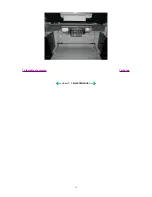


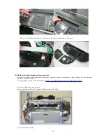
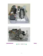


(VI) Remove the scanner unit and FAU cables from the logic board.
- The photo on the left shows the cables connected, and the photo on the right shows the cables removed.
[See Part 3, 2.
CONNECTOR LOCATION AND PIN LAYOUT.]
Note: A square core is taped to the CN602 connector.
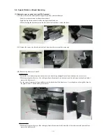
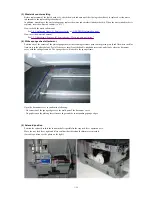
(VII) Remove the scanner stop arm.
- While holding the scanner unit, disengage the main case side of the scanner stop arm.
- While twisting the scanner stop arm, disengage the scanner unit side of the scanner stop arm.
1-18
Summary of Contents for PIXMA MP800
Page 5: ...Part 1 MAINTENANCE ...
Page 9: ...To the table of contents To the top Part 1 1 MAINTENANCE 1 4 ...
Page 38: ...To the table of contents To the top Part 1 3 REPAIR 3 3 3 to 8 1 33 ...
Page 44: ...Part 2 TECHNICAL REFERENCE ...
Page 51: ...To the table of contents To the top Part 2 3 PRINT MODE 2 7 ...
Page 52: ...4 SCAN MODE To the table of contents To the top Part 2 4 SCAN MODE 2 8 ...
Page 58: ...Part 3 APPENDIX ...


