


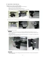


- Also remove the card door which is between the front cover R and the side cover R.
- For the correct locations of claws and bosses on the back side of the front cover R, see the photo on the right (4 claws in
the purple circles, 2 bosses in the green circles).
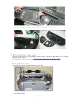
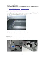
(IV) Remove the cable cover.
- Push the claw of the side cover R (indicated by the triangle mark in the red circle in the photo) with a flat-blade
screwdriver to release.
- Slide the side cover R outward so that the cable cover in the back can be removed.
- Lift the cable cover to remove the FAU cable from the groove of the side cover.
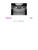
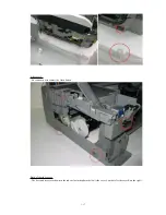
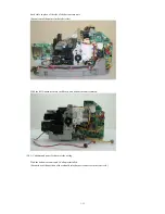
(V) Remove the side cover L and R (3 claws each).
Side cover R:
- Be cautious of the FAU cable, IrDA board, and card LED guide.
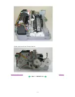
- For the shape of the boss and recess, see the photos below.
- The bosses of the bottom case will fit into the square holes of the side cover.
1-16
Summary of Contents for PIXMA MP800
Page 5: ...Part 1 MAINTENANCE ...
Page 9: ...To the table of contents To the top Part 1 1 MAINTENANCE 1 4 ...
Page 38: ...To the table of contents To the top Part 1 3 REPAIR 3 3 3 to 8 1 33 ...
Page 44: ...Part 2 TECHNICAL REFERENCE ...
Page 51: ...To the table of contents To the top Part 2 3 PRINT MODE 2 7 ...
Page 52: ...4 SCAN MODE To the table of contents To the top Part 2 4 SCAN MODE 2 8 ...
Page 58: ...Part 3 APPENDIX ...


