background image

3.  ERROR DISPLAY 

Errors are displayed by the LEDs, and ink low warnings are displayed by the Status Monitor. 
 

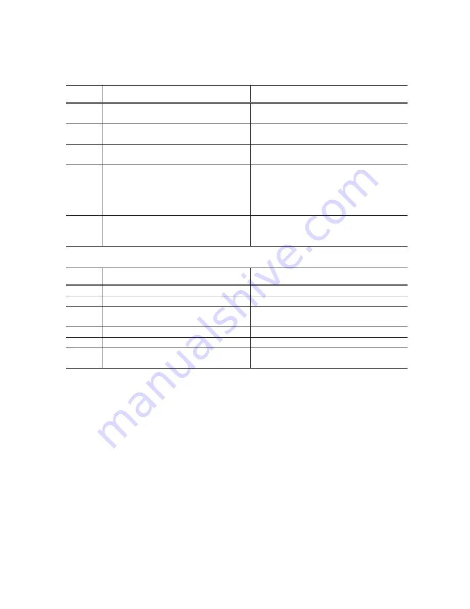
3-1.  Operator Call Error (LED Blinking in Orange) 

LED 

blinking 

Error Corrective 

action 

2 times 

Paper out 

Set paper, and press the Resume/Cancel 
button to feed the paper. 

3 times 

Paper jam 

Remove the jammed paper, and press the 
Resume/Cancel button. 

4 times 

Ink tank not installed 

Re-install the ink tanks, and close the access 
cover. 

5 times 

Print head not installed or failure has 
occurred in the print head. 
(Non-supported print head (see page 4) is 
installed or print head EEPROM data is 
abnormal.) 

Install the print head, and close the access 
cover. Or, confirm the print head is 
“QY6-0044-000” and perform re-installation. If 
not recovered with the print head installed, 
power the printer off and on. 

8 times 

Waste ink absorber full or platen waste ink 
absorber full warning (approx. 95% of the 
maximum capacity) 

Pressing the Resume/Cancel button will exit 
the error, and enable printing. 


3-2.  Service Call Error (LED Blinking in Orange and Green Alternately) 

LED 

blinking 

Error Corrective 

Action 

2 times 

Carriage error 

Replace the printer as it has failed. 

6 times 

Internal temperature error 

Replace the printer as it has failed. 

7 times 

Waste ink absorber full or platen waste ink 
absorber full 

Replace the printer as it has failed. 

8 times 

Print head temperature rise error 

Replace the printer as it has failed. 

9 times 

EEPROM error 

Replace the printer as it has failed. 

10 times  No print head detected excepting print head 

replacement (during printing) 

Replace the printer as it has failed. 


Summary of Contents for PIXMA IP1000

Page 1: ...ONS 3 ERROR DISPLAY 4 SERVICE MODE 5 EXTERNAL VIEW PARTS LIST 6 TROUBLESHOOTING FLOWCHART 7 SPECIAL NOTES ON SERVICING IN ASIA 8 PRODUCT TECHNICAL INFORMATION APPENDIX 1 SHIPMENT INSPECTION PATTERN 1 APPENDIX 2 iP1000 SERVICE TOOL QY8 13A2 010 Rev 01 June 18 2004 Canon Inc ...

Page 2: ...s Product name Product code Sales territory Remarks Canon Ink Tank BCI 24 Black 6881A001AA 6881A002AA 6881A003AA 6881A004AA JPN EUR USA CAN ASIA AUST Canon Ink Tank BCI 24 Color 6882A001AA 6882A002AA 6882A003AA 6882A004AA JPN EUR USA CAN ASIA AUST Canon Ink Tank BCI 24 Black Twin Pack 6881A008AA 6881A009AA 6881A010AA 6881A011AA JPN EUR USA CAN ASIA AUST Canon Ink Tank BCI 24 Color Twin Pack 6882A0...

Page 3: ...oto Stickers 1 sheet T shirt Transfer 1 sheet Borderless printing 4x6 and 5x7 only Detection function Cover open Available Presence of print head Available Presence of ink tank Not available Presence of paper Available Paper width Not available Waste ink absorber full Available Remaining ink amount Available Detected by dot counting Reset by user operation Enabled at default Print head alignment A...

Page 4: ...s in 2 vertical lines C M Y 128 nozzles in 2 vertical lines per color Ink droplet BK 30 pl CL 5 pl Ink color BK pigment based ink CL Y M C high brilliance Ink tank BCI 24 Black BCI 24 Color In common with the S300 S330 i320 i350 i355 i250 and i255 Weight Approx 60g excluding ink tanks Supply method Service part excluding ink tanks Part number QY6 0044 000 In common with the i350 i355 i250 and i255...

Page 5: ...000 and perform re installation If not recovered with the print head installed power the printer off and on 8 times Waste ink absorber full or platen waste ink absorber full warning approx 95 of the maximum capacity Pressing the Resume Cancel button will exit the error and enable printing 3 2 Service Call Error LED Blinking in Orange and Green Alternately LED blinking Error Corrective Action 2 tim...

Page 6: ...emaining ink level detection is enabled and no Status Monitor display when disabled Note The Status Monitor display in the table below is for Windows Warning Display by Status Monitor Ink low warning 1 approx half level Ink low warning 2 low remaining ink Ink low warning 3 ink level unknown ...

Page 7: ...ck pattern printing Significant misalignment can be adjusted 2 Shipment pattern printing ROM version Number of pages fed Waste ink amount Refer to Shipment inspection pattern 1 below Refer to Shipment inspection pattern sample 2 below Host computer and service tool are required EEPROM reset Reset of waste ink counter etc Refer to EEPROM reset Destination setting 3 below Host computer and service t...

Page 8: ... the model name by clicking GET DEVICE ID after setting change If incorrect it can be changed before turning the unit OFF ON EEPROM reset When EEPROM CLEAR is checked the EEPROM is reset after the shipment inspection pattern printing At EEPROM reset the main waste ink counter value is re set to 3 000mg ...

Page 9: ...9 5 EXTERNAL VIEW PARTS LIST 5 1 External Parts Power Supply Unit Logic Board Ass y 5 2 Print Unit ...

Page 10: ...ILM Yes 11 WT2 5694 000 I 1 CLAMP CABLE Yes 12 QC1 1690 000 I 1 LOCK LEVER BLADE Yes 13 QM2 1445 000 I 1 CAP UNIT 14 QM2 1443 000 I 1 BLADE UNIT 15 QA4 1223 000 I 1 ABSORBER1 INK Yes 16 QA4 1255 000 I 1 ABSORBER2 INK Yes S1 XA9 1493 000 G 9 SCREW TP M3X8 FOR AC ADAPTER FOR UPPER CASE UNIT FOR PRINT UNIT Yes S2 XB6 7300 605 G 4 SCREW TP M3X6 MM FOR LOGIC BOARD ASS Y FOR PRINT UNIT LF MOTOR Yes S3 X...

Page 11: ...h 4 SERVICE MODE EEPROM reset Destination setting Since the printer enters the shipping mode carriage in replacement position paper lifting plate raised by powering off using the Power button remove the print head unplug the power cord and do not print afterwards Open access cover and install print head Power ON Service Call Error Connect to computer Shipment inspection pattern printing Service Ca...

Page 12: ...ern printing Nozzle check pattern printing Print head deep cleaning No Correct Correct Correct Correct Nozzle check pattern printing Nozzle check pattern printing Nozzle check pattern printing Refer to 4 SERVICE MODE regarding cleaning method Refer to 4 SERVICE MODE regarding cleaning method Refer to 4 SERVICE MODE regarding printing method Yes Yes Yes Yes No No Print head deep cleaning ...

Page 13: ...nector However in peak periods of production instead of soldering the connector may be used for the CR flexible cable on the print head side Special notes on servicing In replacing the logic board ass y remove the solder from the backside of the logic board s LF and CR motor cable connections and re solder them to the replaced logic board ass y Regarding the CR flexible cable as there is no servic...

Page 14: ...er When the paper is curled and many sheets are loaded the loaded page limit level in the ASF creates friction at paper feeding 4 B Multi feeding Multiple pages of paper are fed simultaneously Blank paper is ejected 1 Fan the paper and set them in the ASF 2 In case of PR 101 set the paper sheet by sheet in the ASF In the high temperature and high humidity environment the frictional force between t...

Page 15: ... to the backside of the following paper 10 C Horizontal lines or uneven print density at the trailing edge of paper Cannot print to the bottom edge of paper Lines or uneven print density appear in the trailing edge of paper Cannot print properly Recommend printing in the print quality assurance area When the paper end comes off the pinch roller printing is performed without the paper being held pr...

Page 16: ...d quality changes and sound becomes quieter Print speed Slows BK printing in HQ HS mode using an acoustic noise measurement pattern Approx 1 3 times 4 Remaining ink level detection function The printer has a function to detect the remaining ink level Default setting ON Detection method Dot counting Counted for each BK CL ink tank CL tank The remaining ink level is detected by total counted dot val...

Page 17: ... consumption when conducting print head deep cleaning repeatedly The amount of ink used is approx 10 to 15 times the normal manual cleaning amount Reference Cleaning types amount of ink used and time required BK and CL ink drawing is simultaneously performed Cleaning type Amount of ink used Time required Manual cleaning Dot count cleaning Timer cleaning 24 hours to 2 weeks BK Approx 0 12 g CL Appr...

Page 18: ...i directional black printing G Print head alignment in bi directional color printing Perform from the printer driver utility At initial set up by the user notice to perform the print head alignment is displayed in the Status Monitor ...

Page 19: ...nk Total area of the sample below Check item 2 Top margin Paper size A4 Print EEPROM information Refer to 4 SERVICE MODE for details C nozzle check pattern BK nozzle check pattern Check item 3 Gray area M nozzle check pattern Y nozzle check pattern Check item 4 Vertical lines ...

Page 20: ...B port number from USB PORT A How to print the shipment inspection pattern 1 Select TEST PATTERN 1 B and the shipment inspection pattern 1 will be printed Refer to APPENDIX 1 SHIPMENT INSPECTION PATTERN 1 How to set the destination 1 In SET DESTINATION C select the model name iP1000 common to all destinations and the destination will be set 2 Click DEVICE ID D and confirm the model name indicated ...

Reviews: