


15
Non-Contact Displacement Sensor User’s Manual Rev 1.00
3.
I/O Terminals
3-1.
Function of I/O Terminals
This section explains the function of I/O terminals.
3-1-1.
Power cable terminals
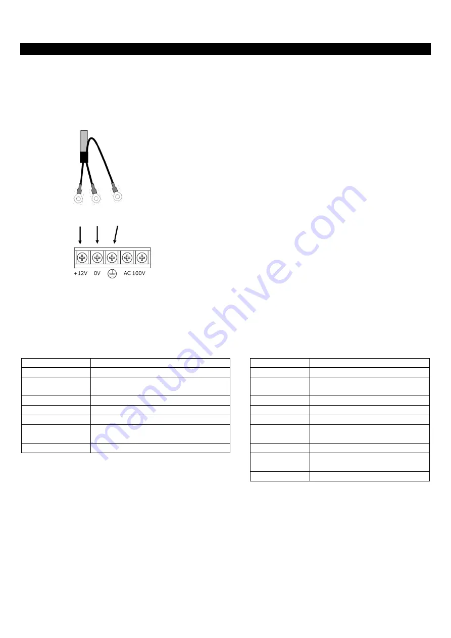
Connect the power cable terminals to the 12 to 24V DC power supplies (Power capacity: 20W or more).
The terminals are ring-shaped for M4.
The following figure shows an example to connect the terminals to 12V DC switching power supplies.
3-1-2.
Connecting the I/O cable
The end of an I/O cable is a ring terminal (for M3, only FG terminal: for M4).
The length of an I/O cable is 5 m. To extend the cable, use a terminal block, etc.
A label is attached to each I/O cable.
The following table shows the relationship between the label display and the function.
Cable Pin Assignment
Label Display
Signal
Label Display
Signal
Phase A pulse
WARNING
Warning signal output
PULSE_A-
Phase A– pulse
WARNING_G Warning signal output GND
(return)
Phase B pulse
RESET
Reset signal input
PULSE_B-
Phase B– pulse
RESET_G
Reset signal input GND (return)
GND
GND
TRIGGER2
Reserve
ERROR
Error signal output
TRIGGER2_G Reserve signal input GND
(return)
ERROR_G
Error signal output GND (return)
TRIGGER1
Trigger signal input
* GND terminals are the same as ones for Phase A/Phase B pulse
output
(RS422 line driver GND).
Connect the Phase A/Phase B pulse receiving circuit as required.
TRIGGER1_G Trigger signal input GND
(return)
FG
FG
* Each return line is floating.
The content of an error or warning can be checked on the bundled application software.
Power cable
DC
12-24V
(Blue)
GND
(White)
FG
(Green)
12V DC switching power supplies